0376
Hybrid Vessel Centerline Tracking: Towards Automated Lesion Analysis on 3D Intracranial Vessel Wall MR1Cedars Sinai Medical Center, Los Angeles, CA, United States, 2Tsinghua University, Beijing, China, 3Beihang University, Beijing, China, 4Xuanwu Hospital, Beijing, China
Synopsis
We proposed a hybrid vessel centerline tracking method on 3D intracranial vessel wall MR. TOF MRA was used as a complementary modality that provides additional information for potential vessel path extraction. Results show high agreement of results from the proposed method and manual rater.
Introduction
3D intracranial vessel wall MR has recently emerged as a method of choice for assessing various arterial wall pathologies. Despite small caliber and curved course in intracranial vessels, detailed lesion interpretation can be achieved by applying advanced image processing methods, such as multiplanar reformation (MPR), to high-resolution 3D images. However, most of the post-processing work currently rely on input from human and is heavily effort demanding and experience dependent. As one of major steps towards automated lesion analysis, vessel centerline tracking has recently gained research interests. In this work, we propose a hybrid tracking method using both dark-blood vessel wall images and bright-blood time-of-flight (TOF) MR angiography (MRA) images.Methods
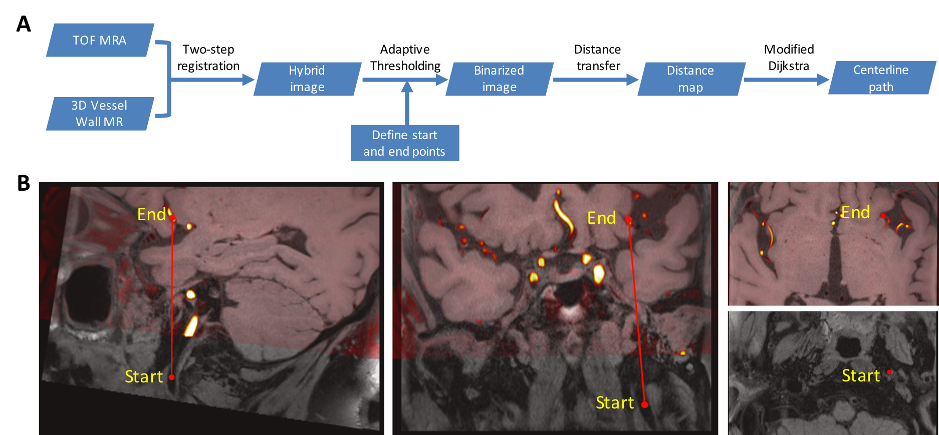
Theory. 3D vessel wall MR and 3D TOF MRA are typically both acquired for intracranial vessel wall assessment. While TOF MRA has relatively limited spatial coverage (with the circle-of-willis as a main target), its high vessel-tissue contrast may facilitate the tracking task at the location of small arterial segments, which is otherwise challenging with vessel wall images only. Our hybrid centerline tracking method, as illustrated in Fig. 1, involves following steps. 1) TOF MRA is co-registered to 3D vessel wall MR using an affine alignment for removing global displacement followed by nonlinear transformation for local shape matching. 2) The aligned TOF MRA and 3D vessel wall MR are combined as a hybrid image set, and after the user assigns the starting and ending points, the hybrid set undergoes image binarization using an adaptive thresholding method based on the histogram of neighboring voxels on the two channels. In this process, the local histograms of starting and ending points are used as reference to binarize non-vessel regions. 3) Distance transformation is then performed to obtain a heat map where voxels inside vessel have higher weights while voxels outside vessel have lower weights. Centerline tracking is performed simultaneously from the starting and ending points. Neighboring nodes are assigned an accumulated weight from the beginning point where the weight is obtained by the sum of distances in the distance map from traveled nodes. Dijkstra algorithm is used to find the shortest path by minimizing the weight. The final centerline path is obtained when two tracks met.
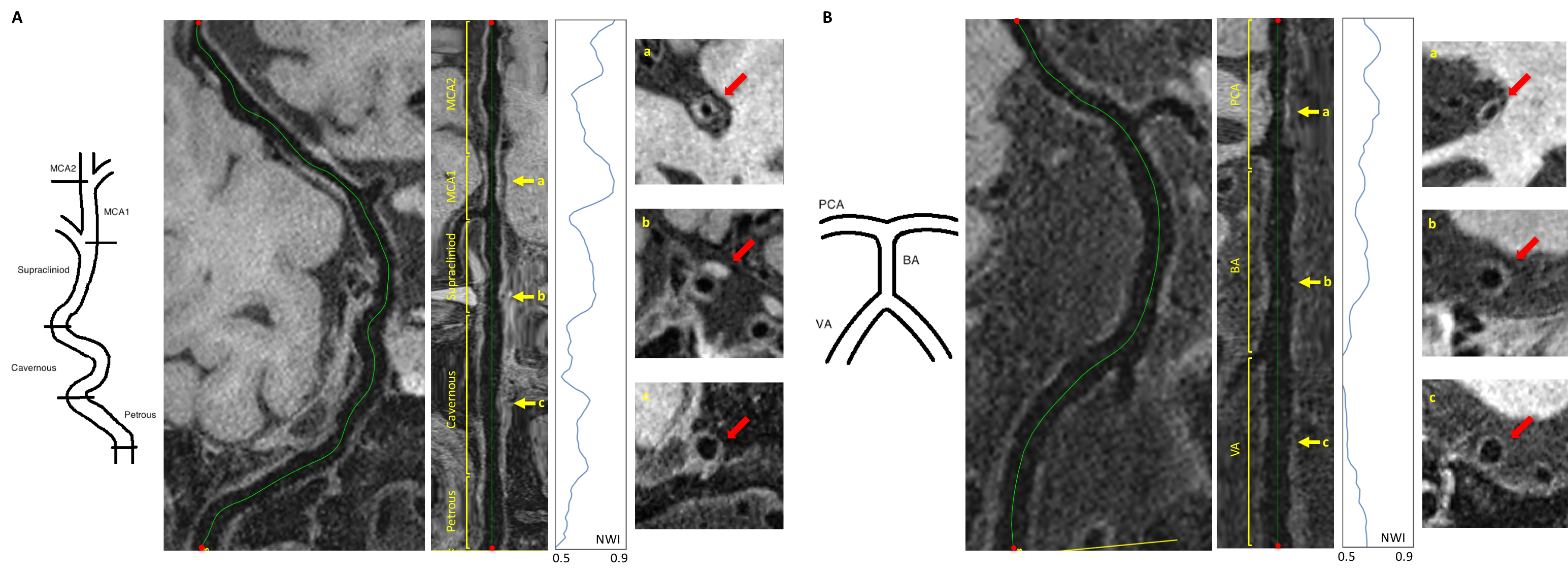
Validation. Imaging data from 8 patients with identified intracranial vessel stenoses were used for validation [1]. Centerline was traced manually (with Horos software) and with the developed automated method, respectively. The two centerlines within the same spatial coverage were compared using the Euclidian distance metric. Additionally, as a demonstration of its utility, the automated method was applied to a patient who has been diagnosed with diffuse vessel wall thickening and a focal aneurysm. Centerline tracking was performed for anterior and posterior circulations and vessel segments were defined. This in turn allowed vessels to be sliced into contiguous cross-sections that underwent vessel wall segmentation and vessel wall normalized wall index (NWI) analysis using our recently proposed intracranial vessel analysis (IVA) framework [2].
Results
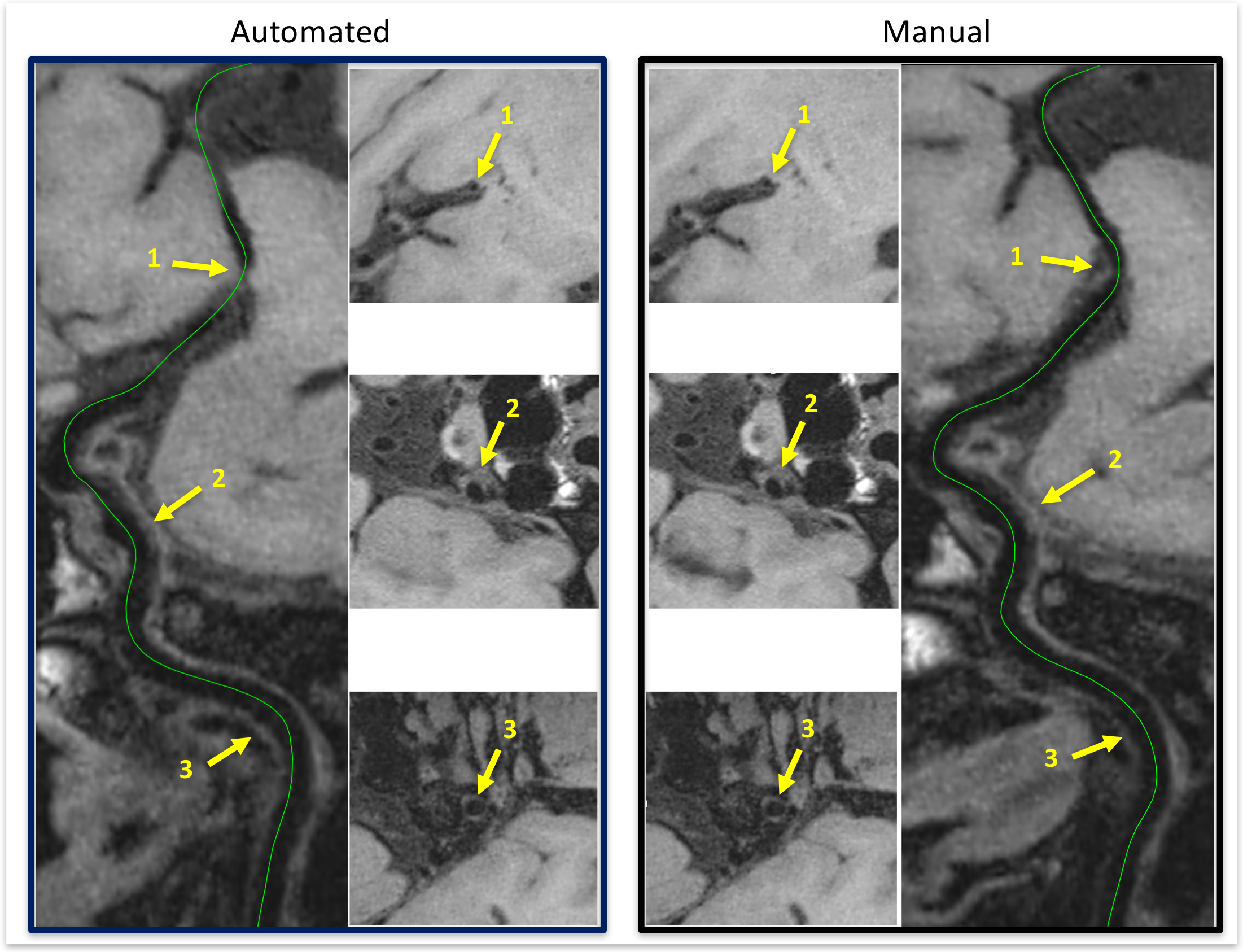
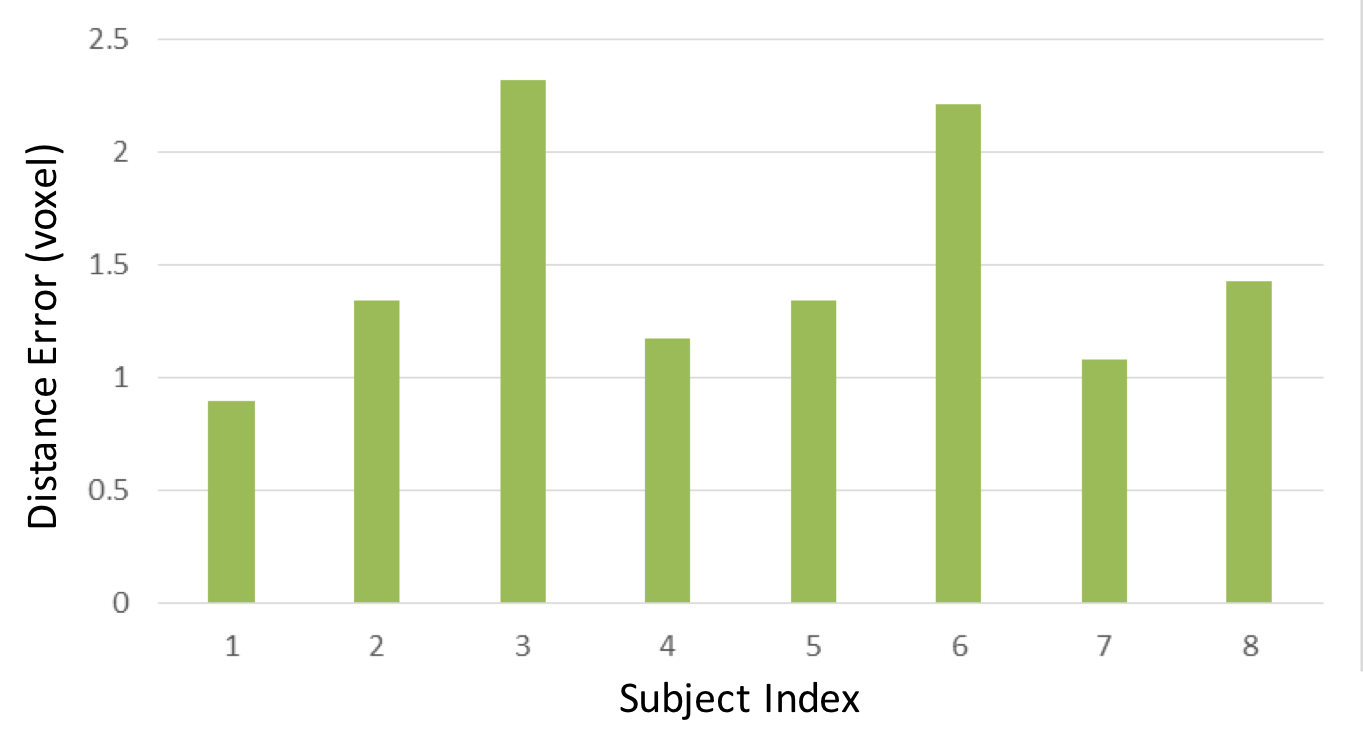
The centerline tracking method yielded comparable curved MPR to the manually traced one in all 8 cases (Fig. 2). The average Euclidian distance error between manual and automated methods were 1.47±0.85 voxels (Fig. 3). Fig. 4 shows the centerlines derived using the automated method for anterior and posterior vascular trees as well as the segment-level NWI analysis. There was good correlation between the calculated NWI values and visually perceived thickening degree in each segment.Discussion
We have developed an automated hybrid vessel centerline tracking method on 3D vessel wall MR with the help of TOF MRA. The method yields comparable quality to manual tracking. With this method, we demonstrated the feasibility of analyzing vessel wall on the segmental basis, which is otherwise time-consuming and potentially unreproducible. It is believed that this method combined with the IVA framework would be useful for rapidly evaluating the entire intracranial circulation and following up therapeutic response in vessel wall pathologies.Acknowledgements
No acknowledgement found.References
[1] Fan Z, Yang Q, Deng Z, Li Y, Bi X, Song S, Li D. Whole brain intracranial vessel wall imaging at 3 Tesla using cerebrospinal fluid attenuated T1 weighted 3D turbo spin echo. Magnetic resonance in medicine 77(3):1142-50, 2017.
[2] Shi F, Yi Z, Yang Q, Li D, and Fan F, Intracranial Vessel Analysis (IVA): A Toolkit for Semi-Automatic Morphological Quantification of Intracranial Atherosclerotic Plaque, ISMRM 4706, Hawaii, USA, April 22-27, 2017.
Figures