0355
A solar powered MR spectrometer system1MRI, ISD Ltd, Bradley, United Kingdom, 2Academic Radiology, University of Sheffield, Sheffield, United Kingdom
Synopsis
Most MRI systems have very high electrical power consumption and require extensive cryogenic support systems. A spectrometer design has been developed for a low cost, low weight and low power specialised MR system capable of ‘unplugged’ operation for worldwide use in remote locations.
Purpose
To develop an ultra low cost, compact, ‘unplugged’ MRI spectrometer for off-grid operation for at least three hours when linked to a permanent imaging magnet.Background and Aims
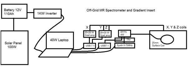
Although mobile MRI systems were developed shortly after the introduction of fixed MRI sites, their scope of operation has been limited to movement along major highways and a requirement for substantial infrastructure in terms of space and electrical power. The aim of this project was to develop a low power MR spectrometer for use with a dedicated 0.2T extremity MRI permanent magnet (InnerVision MRI Ltd., Bradley, UK) which could be run from a standard 12V leisure battery recharged either from a vehicle alternator or from a 100W photo-voltaic solar panel together with a 1KW pure sine wave inverter to provide 240V AC power. It should be possible to mount the entire system including the 500Kg magnet in a small, off-road vehicle for operation in remote locations.Methods
The MR spectrometer was driven from a laptop PC (Vaio, Sony, Japan) interfaced to a USB 7.1 external sound card (Startech, China) which acts as an eight channel waveform control system and a second identical device which was used for two channel data acquisition at rates up to 192KHz. Both devices were powered from the laptop USB sockets. A USB DDS synthesizer (DDS3X25, Hantek, China) was used as the frequency source, again supplied with power from the laptop USB port. The software was programmed in Labview (National Instruments, Austin, TX, USA) and provided full sequence calibration, acquisition, reconstruction and display capability. A 100mm inner diameter insert gradient coil and a 25mm RF surface coil were developed for imaging at 0.2T. Three 20W RMS gradient amplifier channels and a 4W radiofrequency amplifier drove the insert coils. A stabilized DC supply fed from the 240V inverter was used to power the RF transceiver including preamplifiers and drew 0.3A at 12V. A schematic diagram of the complete system (excluding the DC supply) is shown in Figure 1.Results
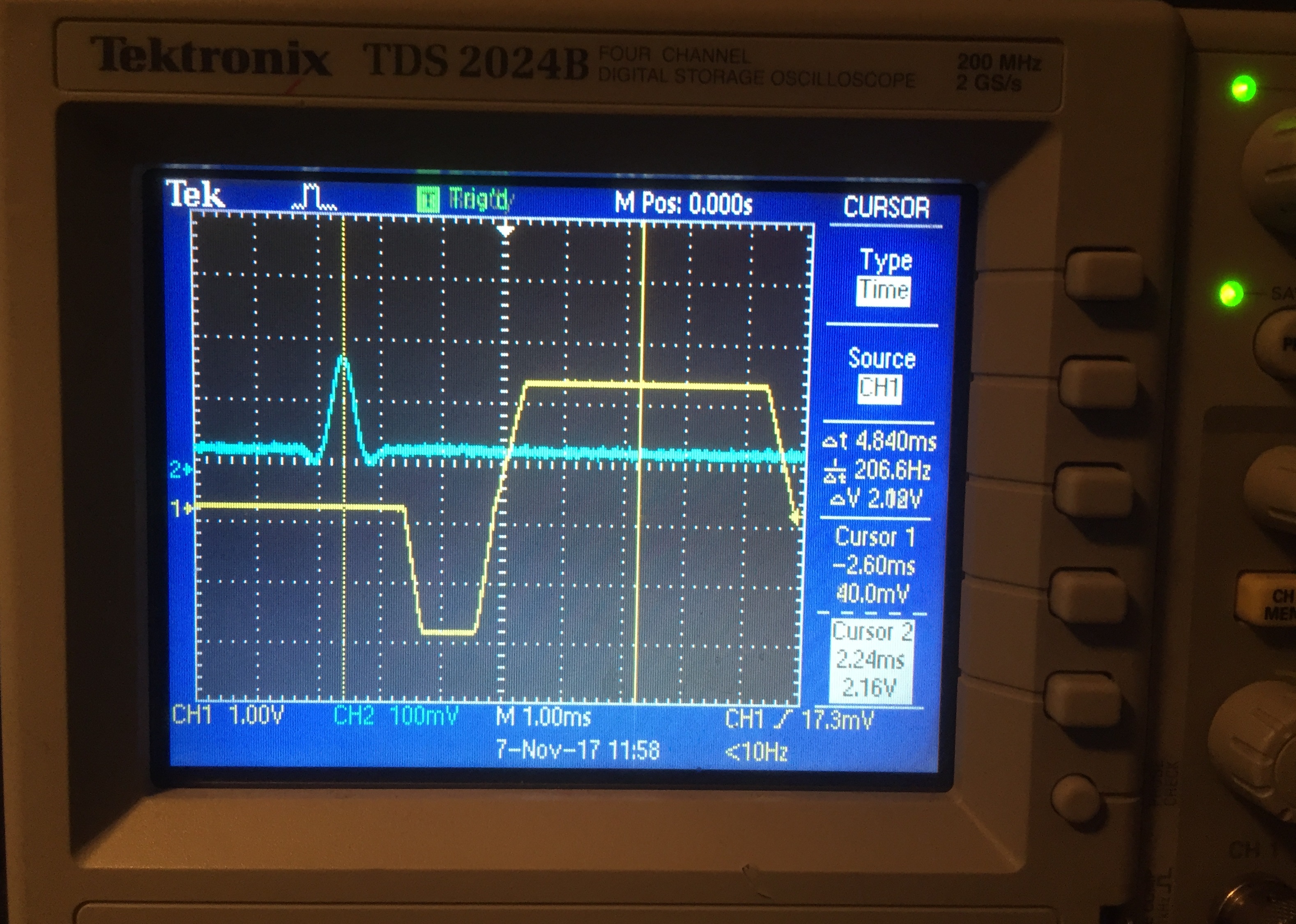
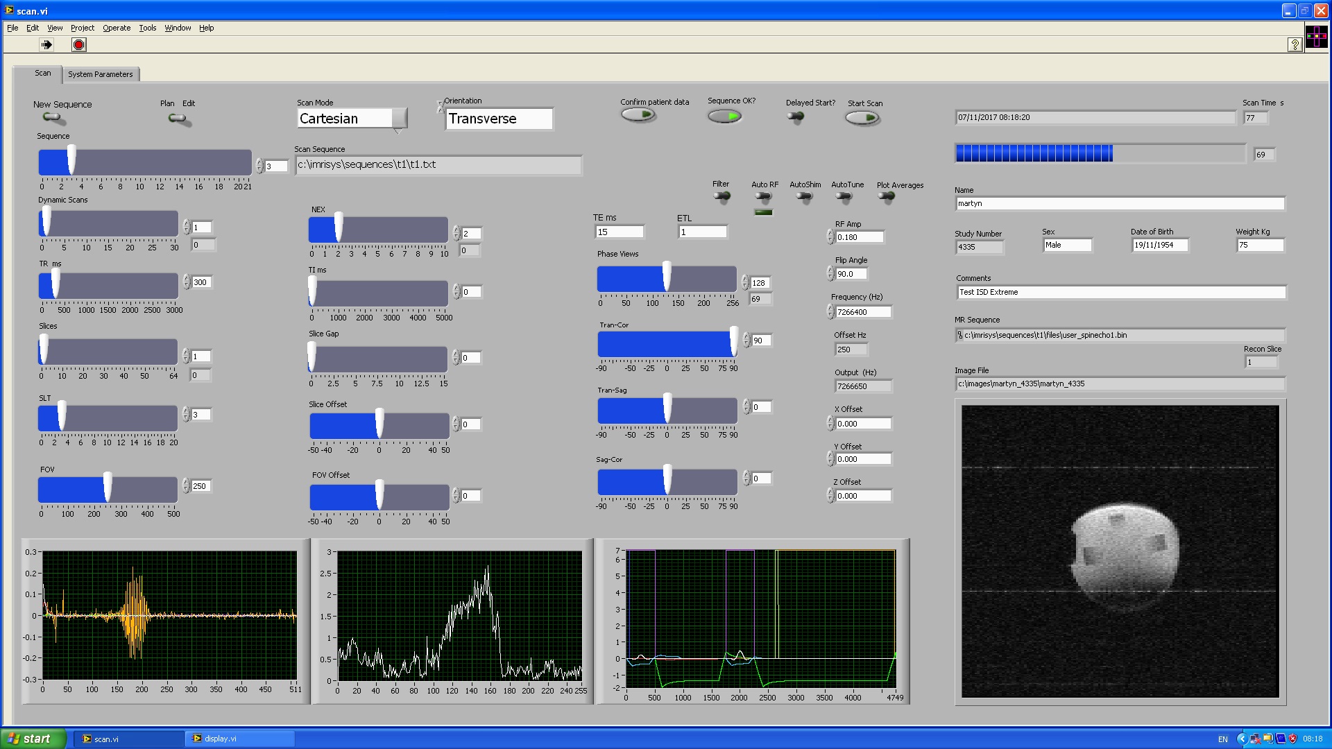
Two of the eight USB 7.1 sound device derived MR waveforms for a gradient echo sequence (RF modulation, frequency readout) are shown in figure 2. The total power consumption of the MR spectrometer/amplifiers operating at maximum gradient and RF amplifier power output was measured at less than 200W allowing operation for over three hours from the fully charged 110Ah leisure battery using the 1KW power inverter without additional charging while continually outputting gradient waveforms to the insert gradient and RF pulses to the surface coil (Sequence parameters, GE, TR 300ms, TE 5ms, 128x256 matrix, NEX=1, continuous dynamic acquisition mode). The battery voltage dropped by just 0.1V over the three hour output period so it should be possible to scan continually with solar panel input to the battery.Discussion and Conclusion
Low power, off-grid operation of a specialized MR system spectrometer seems feasible based on the testing performed here. In an off-line test, a standard 110Ah leisure battery was held at over 12V continually with no load for 3 months using a 100W solar panel while located in North Yorkshire, UK (average sunshine ~5 hours per day in summer). The MR spectrometer, amplifiers and imaging insert were very low cost to build (<$1000 including the laptop) using inexpensive USB7.1 sound devices for the waveform control and data acquisition systems and a low cost but stable DDS frequency source. The solar panel, battery, controller and inverter cost <$500). The small size of the gradient and RF coils means that low power amplifiers can be used to generate adequate gradient strength and RF pulses for extremity imaging. Additional batteries and solar panel capacity would allow for higher power amplifiers to be used.
Acknowledgements
No acknowledgement found.References
1. Paley MNJ, McGinley J, "Specialised MRI Systems: Design, Operation and Economics", 1997, Developments in Magnetic Resonance; 1:76-82.
2. Paley MNJ, Krjukov E, Lamperth M, Young IR. An independent multichannel imaging research system for ultrashort echo time imaging on clinical MR systems `Concepts in Magnetic Resonance Part B: Magnetic Resonance Engineering Volume 35B, Issue 2, pages 80–88, 2009
Figures