0301
Comparison between experimental and simulated electric fields near a hip implant in a parallel transmit hip coil1School of Information Technology and Electrical Engineering, The University of Queensland, Brisbane, Australia, 2School of Public Health and Preventive Medicine, Population Health Research on Electromagnetic Energy, Monash University, Australia, 3Siemens Healthcare Pty Ltd, Brisbane, Australia, 4Centre for Advanced Imaging, The University of Queensland, Brisbane, Australia
Synopsis
The high conductivity of metal implants causes them to focus electric fields in tissue, which may increase the local temperature. In the case of parallel transmit (pTx) MRI, careful simulations of the patient and coil are required to predict heating, but validation of the simulations is challenging near metal implants. In this work, direct measurement of E-field near a hip prosthesis is performed inside a pTx hip coil, and results are compared with simulated data with and without considering decoupling. Neglecting decoupling leads to differences of up to 80% with measured data, showing the importance of realistic simulations.
Purpose
The quality of MRI near metal implants has significantly improved since the introduction of metal artifact reduction sequences1 and MRI has proven superior to CT near hip prostheses in some scenarios2. High-field (≥7T) parallel transmit (pTx) MRI could further improve these results. However, the high conductivity of metal implants causes them to focus electric fields in tissue, which may increase the local temperature3. The current safety testing of implants, involving the measurement of the temperature in gel phantoms4, has not been adapted to pTx where the temperature distribution is shim dependent. Simulations of human models have been proposed as an alternative but will need validation, particularly in the presence of metal implants. B1 and temperature mapping can be used for validation; however their reliability is affected by metal artifacts5,6. Alternatively, temperature probes could provide measurements at a single point, but also require the use of gel phantoms and complex thermal simulations7. We propose to use an E-field probe to measure the electric field near a hip prosthesis to validate the EM simulations.Methods
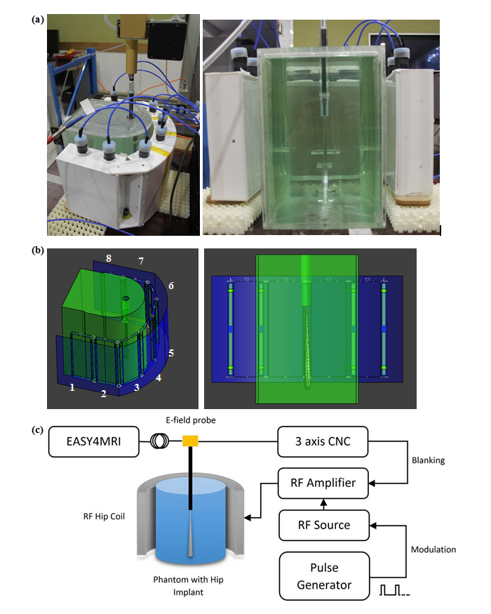
The E-field was measured in a previously presented custom 8-channel pTx hip coil8, tuned to 297.2 MHz (corresponding to 7T). The coil was loaded with a half-elliptical phantom containing a CoCrMo hip implant with its femoral end facing up. A 1mm thick tube was placed in the phantom to give access to a free space E-field probe (ER3DV6, SPEAG), with the tube end in contact with the tip of the metal implant. The E-field probe was moved away from the tip of the implant in the Z-axis every 0.5mm for 15mm with a CNC machine. Each coil was driven individually with 80W, 5 millisecond RF pulses at 25% duty cycle, taking an average E-Field measurement over 20 seconds per position (Fig.1a&c).
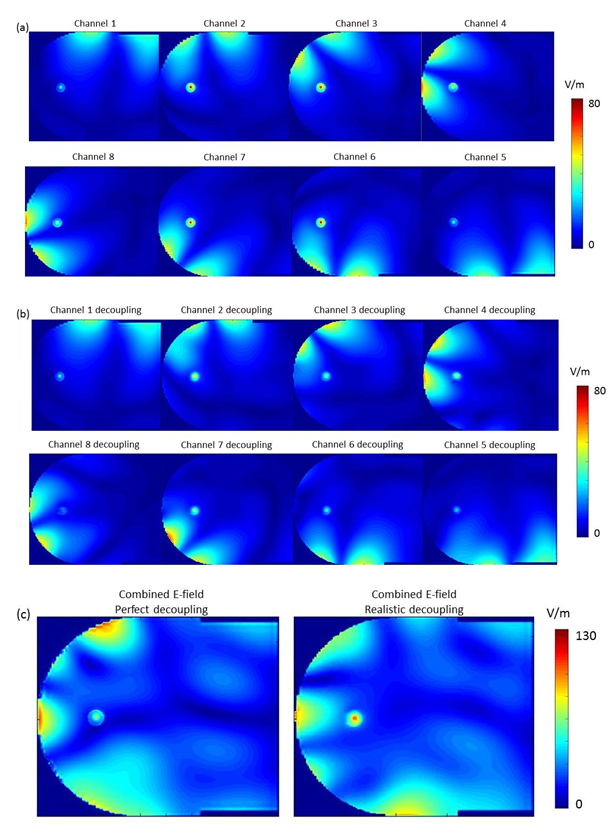
The set-up was accurately modelled in Sim4Life (ZMT, Zurich, Switzwerland) (Fig.1b), and the E-field was calculated using the finite-difference time domain (FDTD) method. Tuning, matching and decoupling were performed by simulating all lumped elements and sources as edge sources, and using co-simulation9 to match these parameters with the measured S-parameters. In addition, each channel was simulated independently, assuming perfect decoupling, to investigate the effect of neglecting decoupling on the E-field. E-fields were exported to Matlab, and interpolated on a 0.5mm grid. A convolution kernel was used on the central axis of the tube, to account for the size of the sensor. A 2D-plot of the E-field along this axis was compared with the measured data, and simulated combined E-fields calculated with and without decoupling were compared.
Results
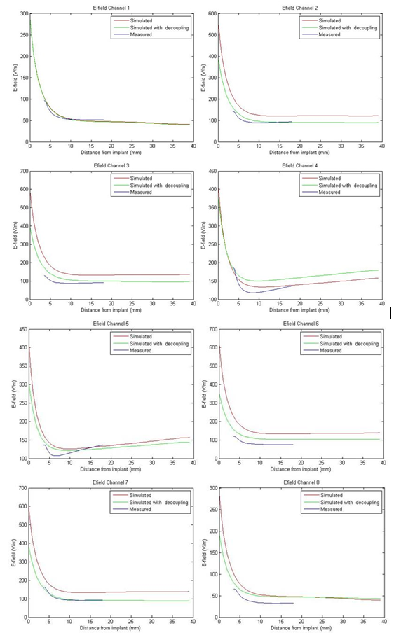
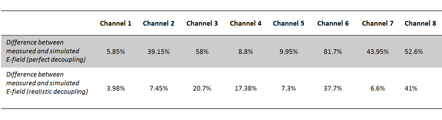
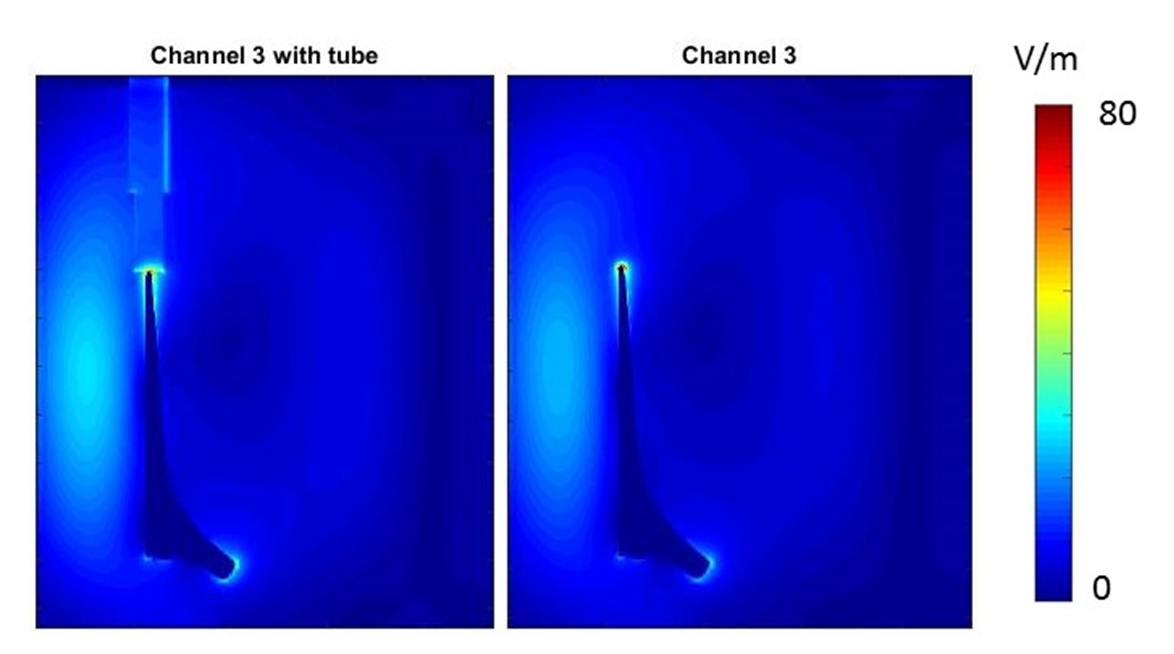
Figure 2 shows the comparison between simulated data and measured E-field for each channel. As summarized in Table 1, including the decoupling networks in the simulation significantly improved the correlation with measured data, with the difference going from an average of 37.5% (and up to 80%) to an average of 17.8%, and as low as 4%, which is in the range of reported data10. For example, in the case of channel 8, decoupling with all other channels was better than -17dB but resulted in a 50% difference with measured data when perfect decoupling was considered. Figure 3 shows the effect of having introduced a tube to accommodate the E-field probe in a coronal slice. Extreme values of the E-field are contained within a few millimetres of the implant, and decrease rapidly to background level. Figure 4a&4b show the individual E-field distribution in the axial slice located at the tip of the implant, and Figure 4c shows an example of combined E-field, when considering perfect and realistic decoupling.Discussion and Conclusion
EM simulations have an important role to play in assessing potential RF heating near metal implants in pTx coils. However, our results show that in order for simulated and measured data to match, perfect decoupling could not be assumed. Although this only resulted in overestimation of the E-field compared to our measurements, this only applies to the case of channels excited independently. As all channels are driven together, phase errors introduced by neglecting decoupling resulted in a 60% underestimation. Because of the complexity of simulating an 8-channel RF coil when decoupling networks are included, validation set ups such as the one used in this study are required.Acknowledgements
The study was funded by the National Health & Medical Research Council (NHMRC) of Australia. M.F. is supported by a NHMRC Centre of Research Excellence grant. We thank and acknowledge Mr Craig Freakly and Rafael Franco for the construction and design of the phantom used in this study.References
1. Hargreaves BA, Worters PW, Pauly KB et al. Metal-induced artifacts in MRI. AJR Am J Roentgenol 2011;197(3):547-555.
2. Bazzocchi A, Bartoloni A, Rimondi E et al. Imaging After Hip Joint Replacement Surgery in the Elderly Population. Current Radiology Reports 2017;5(1):2.
3. Murbach M, Zastrow E, Neufeld E et al. Heating and Safety Concerns of the Radio-Frequency Field in MRI. Current Radiology Reports 2015;3(12):1-9.
4. ASTM. Standard F2182-11a, 2011, standard test method for measurement of radio frequency induced heating on or near passive implants during magnetic resonance imaging. West Conshohocken, PA: ASTM International 2011.
5. Bachschmidt TJ, Kohler M, Nistler J et al. Polarized multichannel transmit MRI to reduce shading near metal implants. Magn Reson Med 2015.
6. Weber H, Taviani V, Yoon D et al. MR thermometry near metallic devices using multispectral imaging. Magn Reson Med 2016.
7. Sammet CL, Yang X, Wassenaar PA et al. RF-related heating assessment of extracranial neurosurgical implants at 7T. Magn Reson Imaging 2013;31(6):1029-1034.
8. Jin J, Weber E, O'Brien K et al. An 8-channel pTx transceive coil for hip imaging at 7 T. 2017; Honolulu, HI, USA.
9. Kozlov M, Turner R. Fast MRI coil analysis based on 3-D electromagnetic and RF circuit co-simulation. J Magn Reson 2009;200(1):147-152.
10. Winter L, Oberacker E, Özerdem C et al. On the RF heating of coronary stents at 7.0 Tesla MRI. Magnetic Resonance in Medicine 2014
Figures