0299
Exploring the impact of nulling currents on a cardiac guidewire in reducing worst case SAR at 1.5T1Division of Imaging Sciences and Biomedical Engineering, King's College London, London, United Kingdom
Synopsis
MRI with non-MR compatible objects, namely wires, poses several challenges as risks of high Local SAR and reduced image quality due to B1 enhancement. In this work we looked at previously proved current nulling techniques and at their relationship with the reduction of worst case SAR scenarios. Results showed that current nulling leads to large reductions in worst case SAR, but that performance varies with coil design and sensor location. The analysis could be used to aid design of experimental setup for maximum safety.
Introduction
Interventional MR and the use of non-MR compatible invasive objects (hereafter referred to as ‘wires’) are usually associated with risks of high local SAR and poor image quality due to B1 enhancement.
Both risk of local hotspots and imaging disruption originate from uncontrolled currents on the wire which are minimised if the wire is decoupled from the transmit system. This is achievable with a parallel transmit architecture combined with sensing wire currents so that transmit weights to apply to each channel can be found which decouple the wire from the RF fields, thus nulling the current1.
Previous demonstrations of the technique have found that full nulling often requires sensing of currents at multiple locations along the wire. Complex current behaviour has previously been investigated experimentally. In this work we used EM simulations to investigate how the nulling approach correlates to the worst case local SAR at the tip of the inserted wire.
Methods
Current sensor ‘nulling’ approaches have used singular value decomposition (SVD) on coupling matrices constructed from one or more sensors; the singular vectors identify modes of the transmit coil that couple to the wire, and the singular values reflect their strength. Meanwhile SAR simulations are usually analyzed using the ‘Q-matrix’2,3 approach. In this case the maximum eigenvalue of a given Q-matrix reflects the worst case SAR at the corresponding spatial location. We used EM simulations (Sim4Life; Zurich MedTech, Zurich, Switzerland) to explore commonalities between these two approaches.
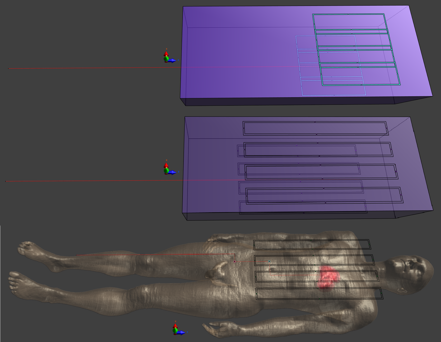
Three scenarios were investigated using two RF coils: 1) short 8-channel Tx/Rx coil on a rectangular phantom (32x10x80cm; $$$\sigma=0.4 S/m$$$; $$$\epsilon=30$$$); 2) long 8-channel Tx/Rx coil - same phantom; 3) long coil on a human model (Duke - ITIS ViP3.1), all at 64MHz (Fig.1). Previous work at 3T suggested that a long coil would be better for nulling currents. In each simulation a wire (core: $$$\varnothing=1mm$$$; insulating layer: 0.1mm thickness) with the distal 5mm stripped of insulation was inserted into the phantom/body. To reduce computation time, the Huygens Box method, implemented in Sim4Life, was applied to all simulations in a region surrounding the wire. Analysis was performed in MATLAB.
Pointwise Q-matrices and surface current on the wire (J) were extracted from the models. Q-matrices were normalised to the average B1+ under each coil when driven in a nominal quadrature configuration (to account for differences in efficiency). Eigenvalue decomposition of a Q-matrix from a point near the tip of the wire was used to determine worst case SAR configuration.J was sampled at points along the wire in order to synthesize current sensor readings. A number of different sensing configurations were tested, including different combinations of one or two sensing locations inside and outside the phantom/body. For each configuration, the coupling modes were identified using SVD, and then the Q-matrix was projected onto the sub-space defined by excluding one or more of the strongest coupling modes. Eigenvalue decomposition of this projected Q-matrix helps to quantify the remaining worst case SAR at the wire tip (rwcSARTIP).
Results & Discussion
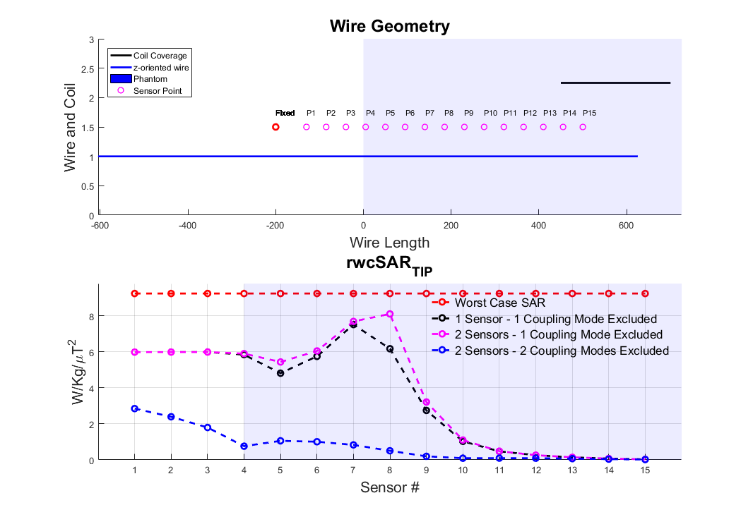
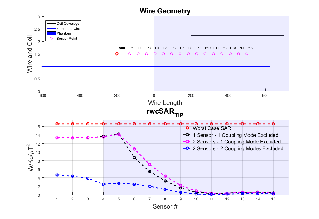
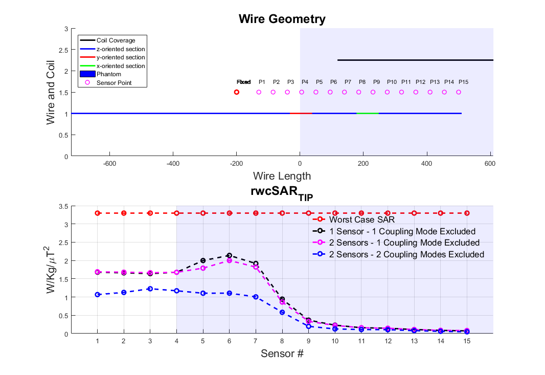
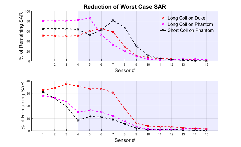
Figures 2,3 and 4 show worst case tip-SAR for coupling modes identified by one or two sensors; for the two-sensor cases, one remains fixed outside the object, while the other takes the position indicated on the figure. For all scenarios, excluding the first coupling mode leads to a definite reduction in rwcSARTIP. Also, in all scenarios, the reduction reaches values around 10% of the original worst case SAR as the sensing point progresses into the phantom/body. This reduction is however dependent on sensor placement, and it appears that two sensors, with one inside the object, are necessary for reliable reduction in rwcSARTIP. Further, when using two sensors, it is necessary to exclude both coupling modes that are identified in order to mitigate rwcSARTIP. Figure 5 compares these approaches and shows that if only one sensor is to be used, a longer coil ensures better ability to mitigate worst-case heating, whereas for two sensors, the shorter coil is better.Conclusion
This work has attempted to quantify worst case SAR when using a ‘decoupling’ approach based on current measurements on inserted wires. It has previously been shown that multiple sensors are required in order to fully null induced currents1 however quantification of residual risk and evaluation of numbers of required sensing points or coil designs has not been straightforward. By projecting the local SAR (“Q”) matrices into the subspace defined by identified decoupling modes, we have shown that large reductions in worst case SAR are possible, but that care must be taken over the exact design in order to fully mitigate dangerous heating scenarios.Acknowledgements
JNT is funded by MRC CASE studentship [MR/P01674X/1]. This work was supported by the Wellcome EPSRC Centre for Medical Engineering at Kings College London [WT 203148/Z/16/Z], MRC strategic grant [MR/K006355/1], MRC development pathways funding scheme [MR/N027949/1], and by the National Institute for Health Research (NIHR) Biomedical Research Centre based at Guy’s and St Thomas’ NHS Foundation Trust and King’s College London. The views expressed are those of the authors and not necessarily those of the NHS, the NIHR or the Department of Health.References
1. Etezadi-Amoli M, Stang P, Kerr A, Pauly J, Scott G. Controlling radiofrequency-induced currents in guidewires using parallel transmit. Magn Reson Med. 2015;74(6):1790-1802. doi:10.1002/mrm.25543.
2. Graesslin, I., Homann, H., Biederer, S., Börnert, P., Nehrke, K., Vernickel, P., Mens, G., Harvey, P. and Katscher, U. A specific absorption rate prediction concept for parallel transmission MR. Magn Reson in Med. 2012; 68(5):1664-1674. doi: 10.1002/mrm.24138
3. Eichfelder, G. and Gebhardt, M. Local specific absorption rate control for parallel transmission by virtual observation points. Magn Reson in Med. 2011; 66(5): 1468-1476. doi: 10.1002/mrm.22927
Figures