0297
Optimizing the Topography of Transmit Coils for SAR Management1Electrical and Electronics Engineering Department, Bilkent University, Ankara, Turkey, 2National Magnetic Resonance Research Center (UMRAM), Ankara, Turkey, 3Athinoula A. Martinos Center for Biomedical Imaging, Department of Radiology, Massachusetts General Hospital and Harvard Medical School, Charlestown, MA, United States, 4Center for Magnetic Resonance Research (CMRR), University of Minnesota, Minneapolis, MN, United States
Synopsis
Specific absorption rate (SAR) is a significant issue for ultra-high field (UHF, B0≥7T) imaging. In this study, we investigate a strategy based on optimizing the topography of transmit elements in 3D (i.e., adding bumps to a resonant planar structure) in order to reduce the local SAR while keeping B1+ efficiency constant inside a region of interest. For proof of concept, we modified three different resonant structures and compared their performance to previous designs with EM simulations. In addition, we built one of the proposed design and experimentally tested it using a whole-body 10.5T scanner.
Introduction
The demand for ultra-high field MRI (UHF, B0≥7T) is continuously increasing due to its numerous benefits,1-3 however, concerns over accompanying increases in the peak local specific absorption rate (SAR) is a limiting factor in many applications.4,5 The increase in SAR is a result of shorter wavelengths at higher frequencies and complex interferences of the electromagnetic fields. Using transmit array (TxArray) coils with improved SAR performance may provide a good solution for this issue.6,7
Recently, some structures such as 3D curved,8 fractionated,9,10 and snake11 dipole antennas were proposed to improve the SAR efficiency of TxArray coils at UHF, however, continued improvements are needed especially for deep-body imaging applications. In such applications, generating an acceptable level of B1+ at a target organ may increase the peak local SAR significantly.
In this study, we propose to modify the geometry of individual coil elements by placing a bump underneath the discontinuities (i.e., all lumped elements and excitation ports) on the coil. This reduces the peak local SAR while B1+ almost remains constant at the intended depth. For proof of concept, we performed the corresponding simulations for different types of coils and constructed a modified fractionated dipole as described. In addition, we conducted phantom experiments on a whole-body 10.5T scanner.
Theory and Method
The discontinuity on the current pathway leads to charge accumulation which results in elevated electric fields and SAR levels in the tissue. Placing a bump underneath the discontinuity increases the distance between the accumulated charges and the body. As a result, it reduces the electric field generated by these charges inside the tissue. On the other hand, the B1+ at a point which is sufficiently far from the coil is not affected by this modification.
Simulation
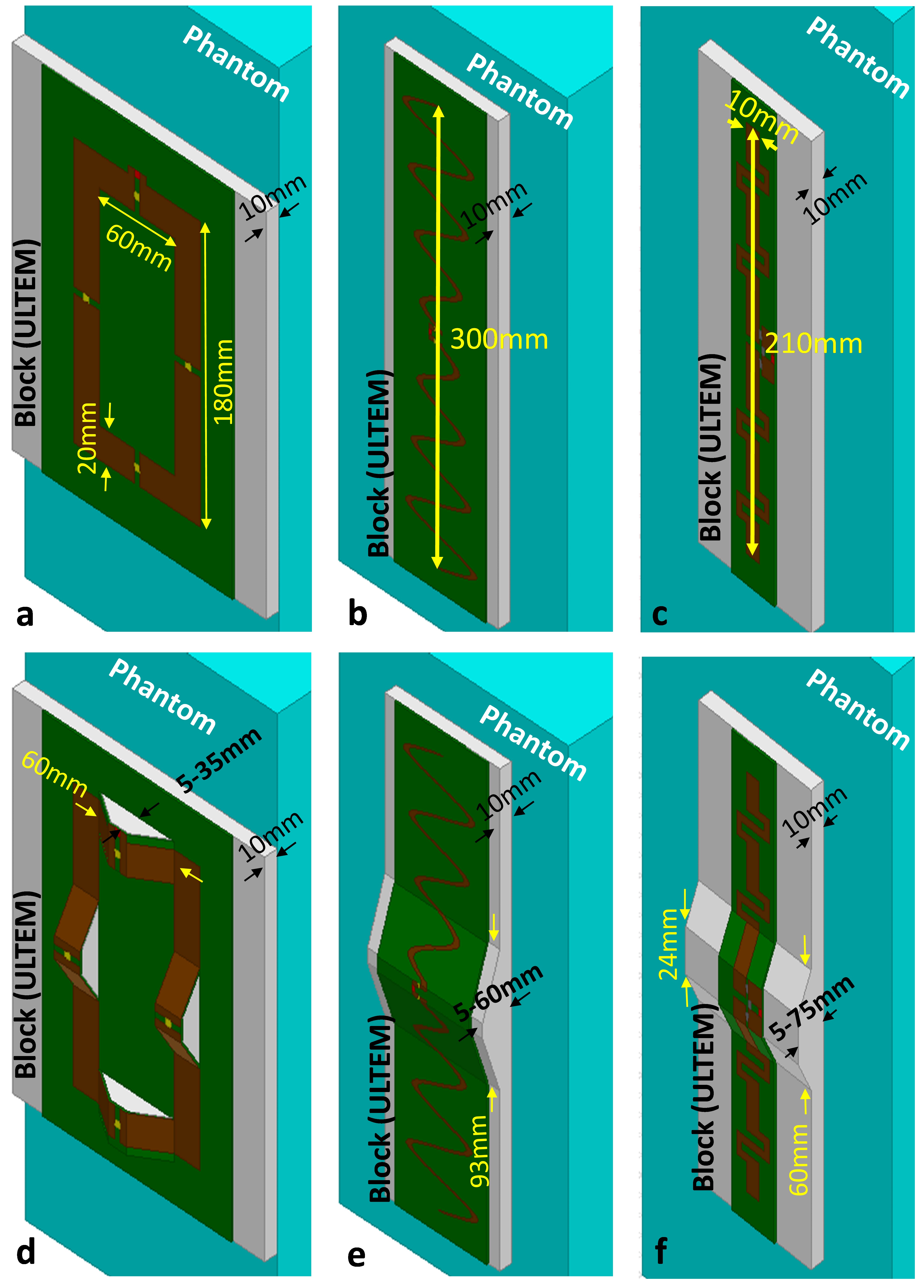
According to this scenario, simple bumps were placed at discontinuities of a loop coil,12 the snake dipole,11 and the fractionated dipole10 as shown in Fig. 1. In each case, a deep-body target was defined, and accordingly, the following optimization problem was investigated by sweeping the height in a reasonable range.
minimize {peak 10g average SAR}
subject to {B1+ remains constant at the depth of 5 to 12cm, compared to conventional structure}
We performed simulations with an EM simulator (HFSS, ANSYS, Canonsburg, PA, USA). For the unmodified dipole, conductors were located on a PCB which was mounted on a thermoplastic polyetherimide block (ULTEM 1000 resin, Sabic Global, Pittsfield, MA). For the modified dipole, conductors were placed on a block of polyethylene terephthalate (PETG).
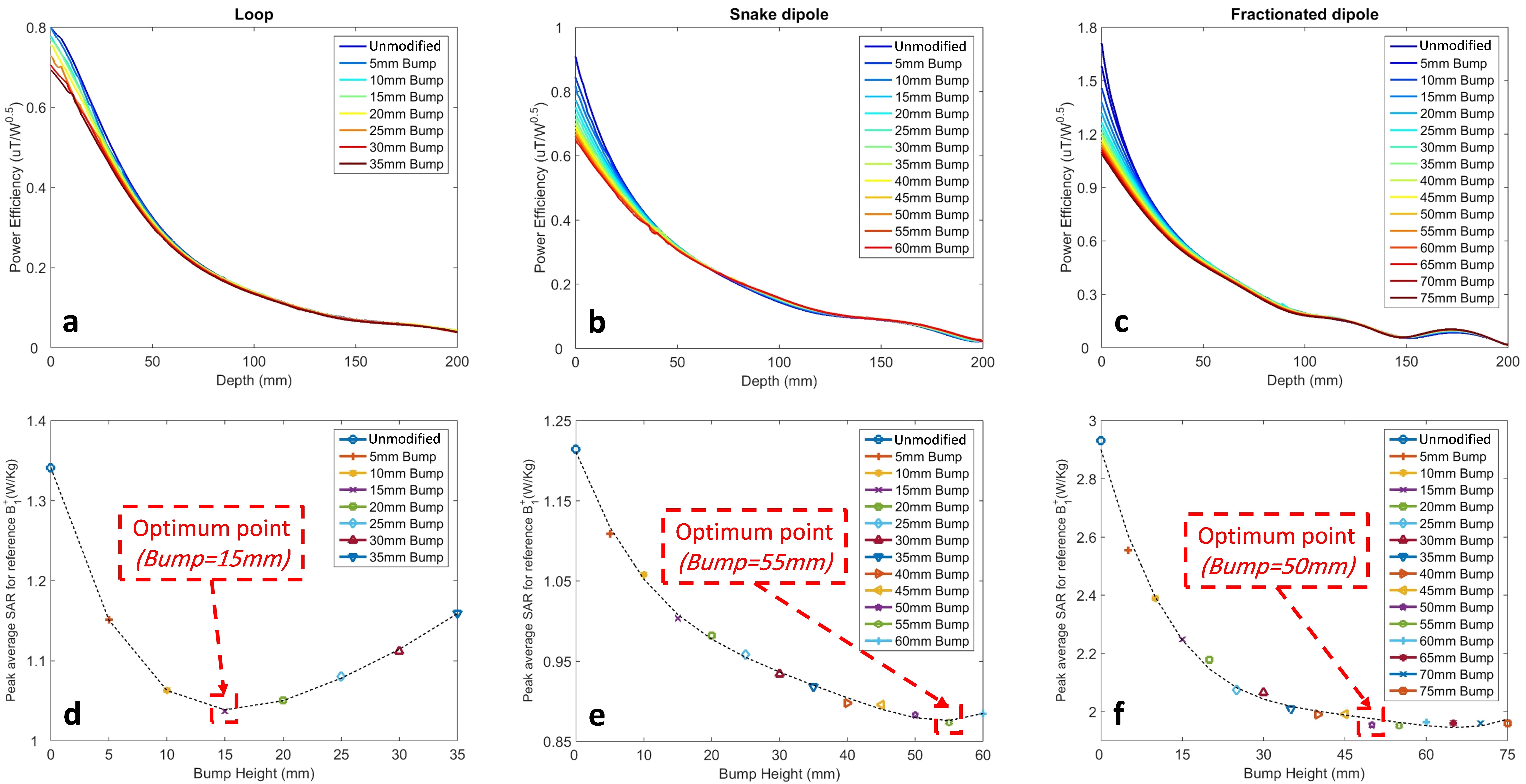
Fig. 2a-c shows the power-efficiencies ($$$\frac{B_1^+}{\sqrt{input\ power}}$$$) for each coil on a line perpendicular to the coil surface and passing through coil’s center. The effect of different bump heights can also be seen in the figures. Note that different bump heights did not change the power-efficiency away from the coil (i.e., depth >50 mm). In Fig. 2d-f, the power-efficiency at a depth of 8cm was chosen as a reference and peak 10g average SAR was determined for the reference power-efficiency for each height.
Experiment
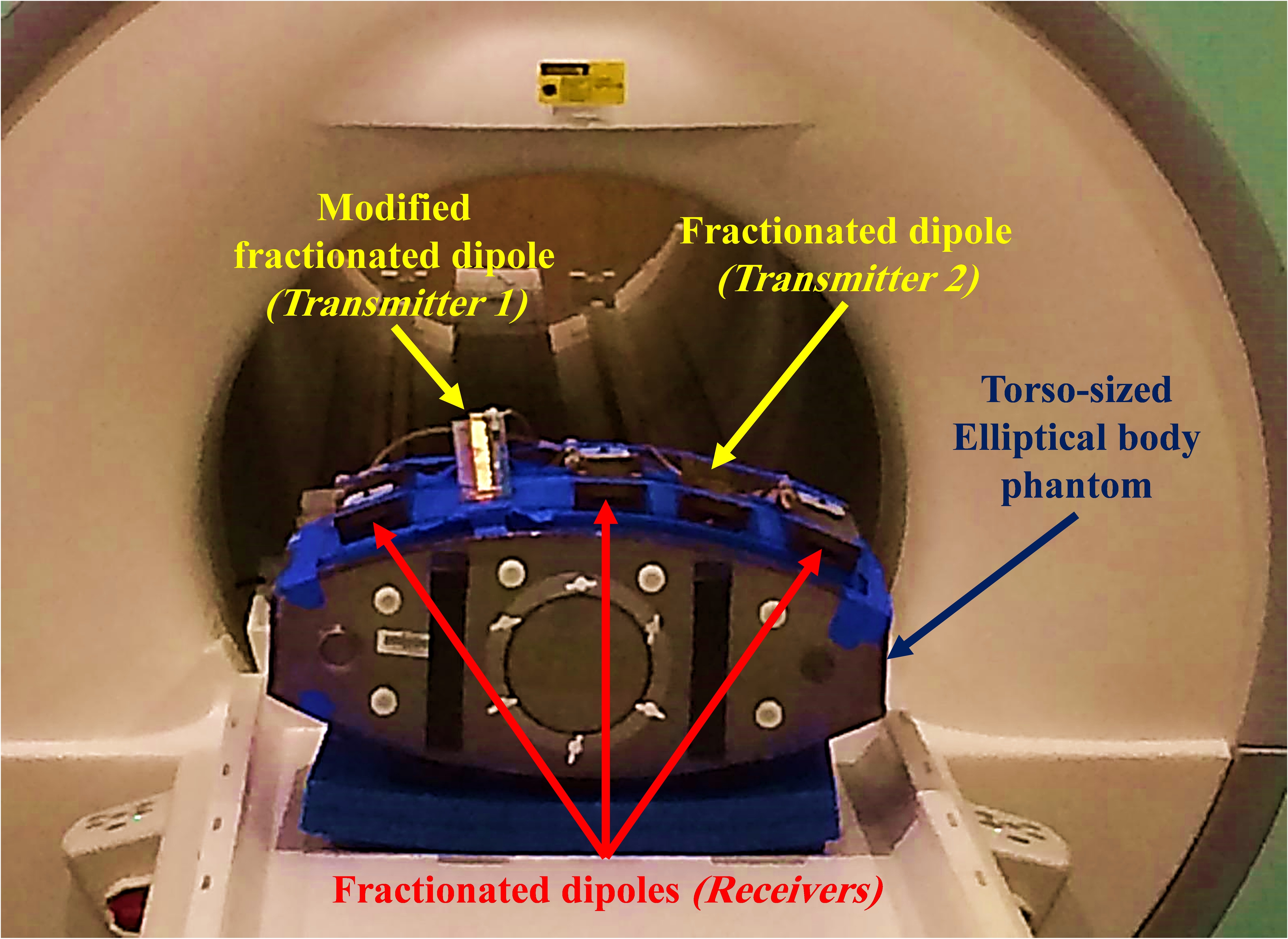
For the experimental setup (Fig. 3), we built a fractionated dipole with a 5cm bump located underneath the excitation port. Both unmodified and modified fractionated dipoles were placed 10cm away from each other, on the phantom. The MRI experiments were conducted on a 10.5T whole-body scanner (Siemens Healthcare, Erlangen, Germany) and B1-maps were obtained using the actual flip-angle imaging13 (AFI) technique. In addition, temperature mapping was performed based on the Proton Resonance Offset method14,15 with a multi-echo gradient-echo pulse sequence.
Results
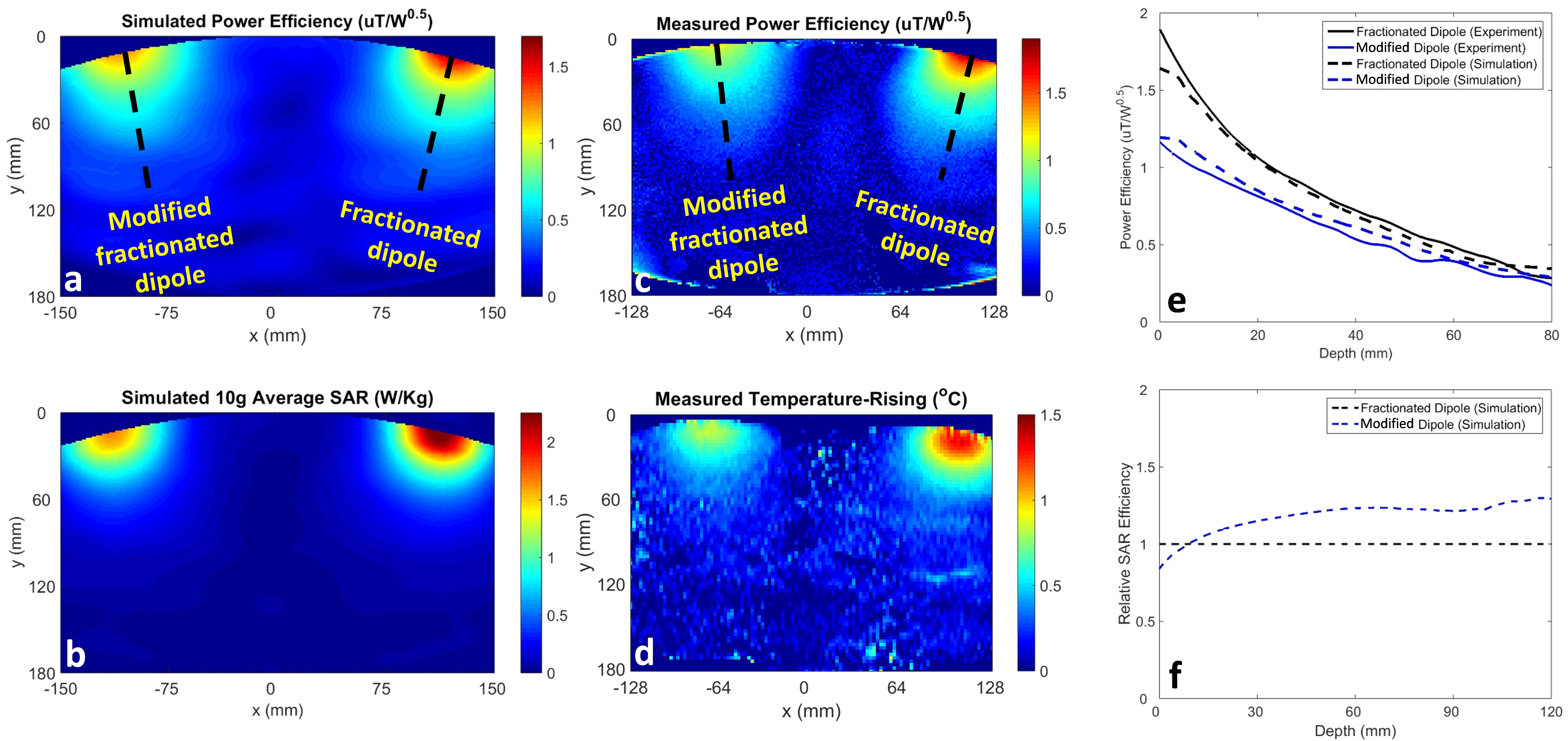
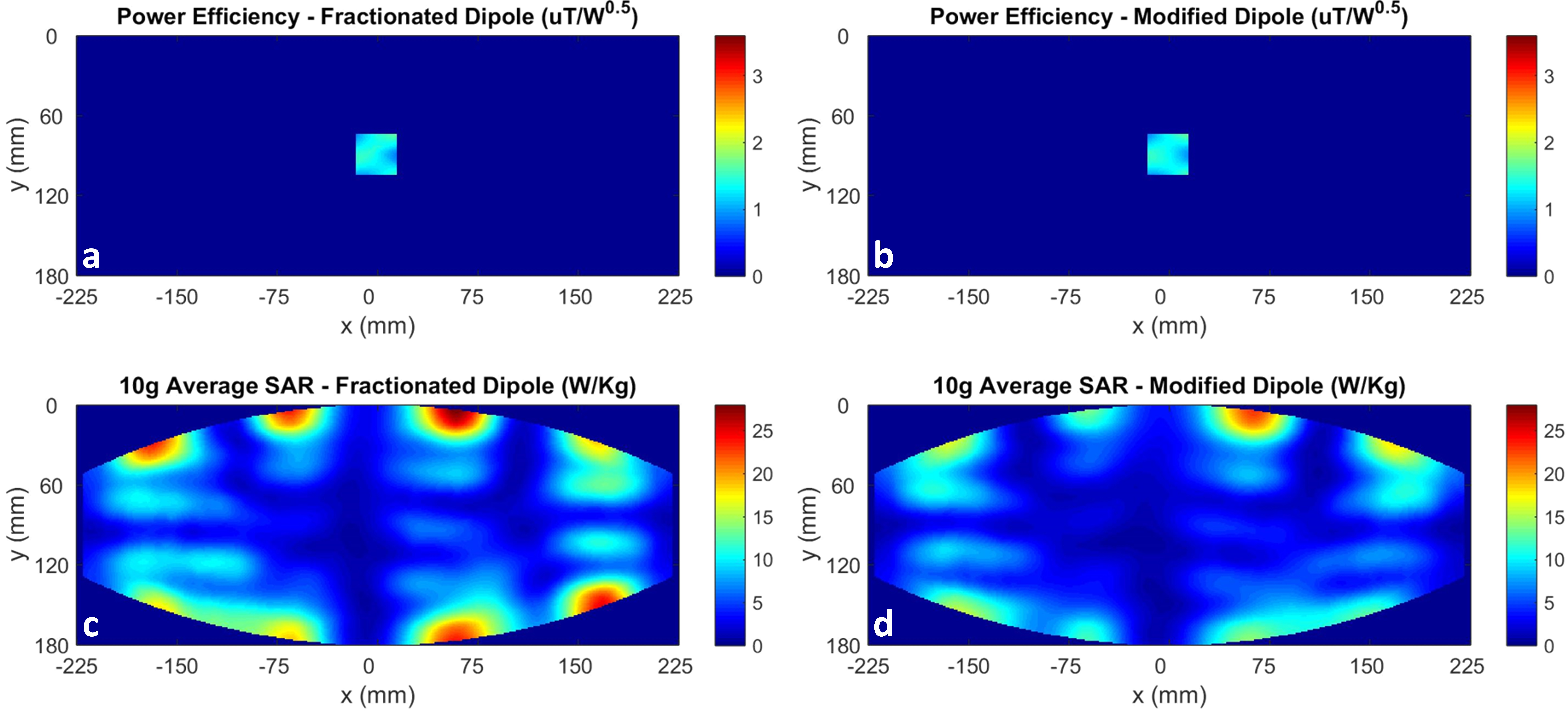
Fig. 4a-b show the power-efficiency and 10g average SAR maps, respectively, obtained using EM simulations of modified and unmodified fractionated dipoles located on the torso-sized phantom. Fig. 4c shows the power-efficiency map acquired using an MRI experiment while Fig. 4d shows the corresponding temperature map. The power-efficiencies along the line perpendicular to the coils (indicated as black dashed lines in Fig. 4a and 4c) are presented in Fig. 4e. According to the simulation results and considering the organs at the depth of 5 to 12cm inside the body, Fig. 4f shows from 22% to 30% improvement in SAR-efficiency ($$$\frac{B_1^+}{\sqrt{peak\ 10g\ average\ SAR}}$$$).
Comparing the performance of the modified and unmodified fractionated dipole array, Fig. 5 shows a 22% reduction in the peak 10g average SAR.
Conclusion
In this work, we investigated a coil design strategy based on optimizing the topography of transmit elements in 3D (i.e., adding bumps to a resonant planar structure) in order to reduce the local SAR. As an example, we modified a fractionated dipole and performed EM simulations and MRI experiments with a 10.5T scanner. Results show that the SAR efficiency can be improved up to 30%.Acknowledgements
This work was supported by NIH grants (P41 EB015894 and S10 RR029672).References
1. Cho ZH, Kang CK, Han JY, Kim SH, Kim KN, Hong SM, Park CW, Kim YB. Observation of the lenticulostriate arteries in the human brain in vivo using 7.0 T MR angiography. Stroke 2008;39:1604–1606.
2. Duyn JH, van Gelderen P, Li TQ, de Zwart JA, Koretsky AP, Fukunaga M. High-field MRI of brain cortical substructure based on signal phase. Proc Natl Acad Sci USA 2007;104:11796–11801.
3. Nakada T, Matsuzawa H, Igarashi H, Fujii Y, Kwee IL. In vivo visualization of senile-plaque-like pathology in Alzheimer’s disease patients by MR microscopy on a 7 T system. J Neuroimaging 2008;18:125–129.
4. Hoult DI. Sensitivity and power deposition in a high-field imaging experiment. J Magn Reson Imaging 2000;12:46–67.
5. Collins CM, Smith MB. Calculations of B(1) distribution, SNR, and SAR for a surface coil adjacent to an anatomically-accurate human body model. Magn Reson Med 2001;45:692–699.
6. Adriany, G., Van de Moortele, P.-F., Wiesinger, F., Moeller, S., Strupp, J. P., Andersen, P., Snyder, C., Zhang, X., Chen, W., Pruessmann, K. P., Boesiger, P., Vaughan, T. and Uğurbil, K. (2005), Transmit and receive transmission line arrays for 7 Tesla parallel imaging. Magn. Reson. Med., 53: 434–445. doi:10.1002/mrm.20321.
7. Metzger GJ, Snyder C, Akgun C, Vaughan T, Ugurbil K, Van de Moortele PF. Local B1 shimming for prostate imaging with transceiver arrays at 7T based on subject-dependent transmit phase measurements. Magn Reson Med 2008;59:396–409.
8. Chen G, Sodickson D, Wiggins G. 3D curved electric dipole antenna for propagation delay compensation. In Proceedings of the 23nd Annual Meeting of ISMRM, Toronto, Canada, 857 (2015).
9. Raaijmakers AJ, Italiaander M, Voogt IJ, Luijten PR, Hoogduin JM, Klomp DW, van den Berg CA. The fractionated dipole antenna: A new antenna for body imaging at 7 Tesla. Magnetic resonance in medicine. 2016 Mar 1;75(3):1366-74.
10. Ertürk MA, Wu X, Eryaman Y, Moortele PF, Auerbach EJ, Lagore RL, DelaBarre L, Vaughan JT, Uğurbil K, Adriany G, Metzger GJ. Toward imaging the body at 10.5 tesla. Magnetic resonance in medicine. 2017 Jan 1;77(1):434-43.
11. Steensma B, Andrade AV, Klomp D, Van den Berg CA, Luijten P, Raaijmakers A. Body imaging at 7 Tesla with much lower SAR levels: an introduction of the Snake Antenna array. InProceedings of the 24th Annual Meeting of ISMRM, Singapore 2016.
12. Thalhammer C, Renz W, Winter L, Hezel F, Rieger J, Pfeiffer H, Graessl A, Seifert F, Hoffmann W, von Knobelsdorff‐Brenkenhoff F, Tkachenko V. Two‐Dimensional sixteen channel transmit/receive coil array for cardiac MRI at 7.0 T: Design, evaluation, and application. Journal of Magnetic Resonance Imaging. 2012 Oct 1;36(4):847-57.
13. Yarnykh VL. Actual flip‐angle imaging in the pulsed steady state: a method for rapid three‐dimensional mapping of the transmitted radiofrequency field. Magnetic resonance in Medicine. 2007 Jan 1;57(1):192-200.
14. Poorter JD, Wagter CD, Deene YD, Thomsen C, Ståhlberg F, Achten E. Noninvasive MRI thermometry with the proton resonance frequency (PRF) method: in vivo results in human muscle. Magnetic resonance in medicine. 1995 Jan 1;33(1):74-81.
15. Kuroda K, Oshio K, Chung AH, Hynynen K, Jolesz FA. Temperature mapping using the water proton chemical shift: a chemical shift select.
Figures