0172
MR Fingerprinting (MRF) incorporating simultaneous detection of RF transmit field and B0 inhomogeneity1State Key Laboratory of Modern Optical Instrumentation, College of Optical Science and Engineering, Zhejiang University, Hangzhou, China, 2Center for Brain Imaging Science and Technology, Department of Biomedical Engineering, Zhejiang University, Hangzhou, China
Synopsis
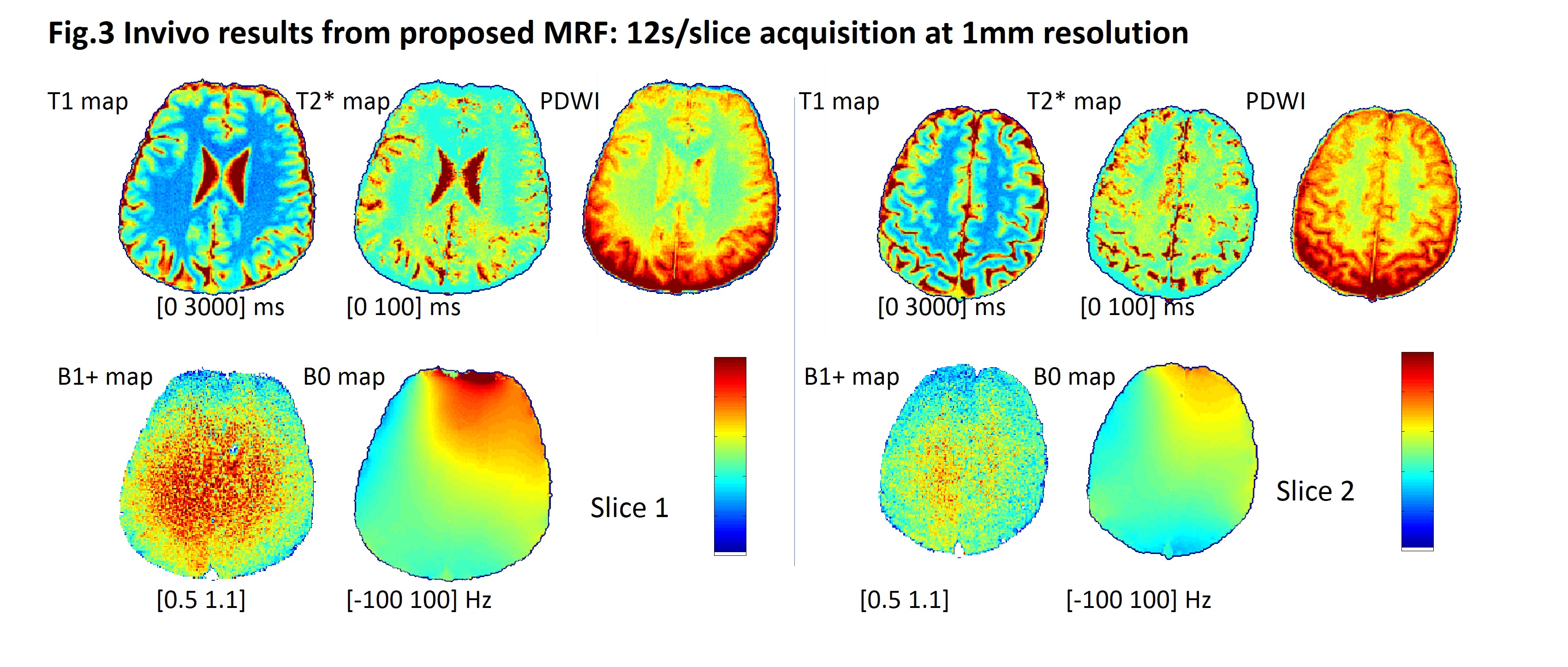
MR fingerprinting with B1+ and B0 field inhomogeneity detection is proposed with an IR-spoiled GRE based sequence. With this sequence, a 12s/slice acquisition simultaneously provide unbiased T1, T2* maps and B1+, B0 information at isotropic 1mm resolution.
Introduction
MR fingerprinting (MRF) (1) has been widely investigated for its acquisition, reconstruction and applications. Similar to some other quantitative methods, the MRF-derived parameter values are prone to systematic errors, such as RF transmit field (B1+) and B0 field inhomogeneity. There have been researches on high field and/or parallel transmission system to incorporate the B1+ effects into the MRF framework (2,3), or using additionally acquired B1+ maps to compensate for MRF mapping inaccuracy (4). As for the B0 inhomogeneity, it can be retrieved from the IR-trueFISP based MRF while the map is degraded by the banding artifact (1). Here we propose to use the IR-spoiled GRE with double TR and various TEs to enable a simultaneous T1, T2*, B1+ and B0 field inhomogeneity detection in MRF.Methods
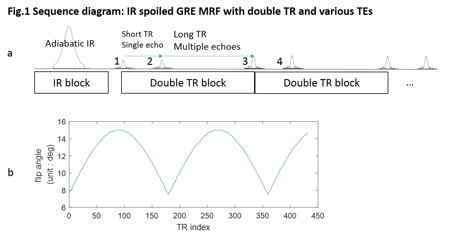
Fig.1a shows the proposed sequence diagram of the IR spoiled GRE MRF with double TR and various TEs, the sequence can be divided into one IR block and multiple double TR block. The IR block is inserted at first for its high efficiency and accuracy for T1 mapping, as prerequisite for mapping the B1+ accurately. The double TR block uses a short TR and a long TR which is adopted from the conventional B1 mapping method AFI (5) to encode the B1+ information. In the long TR, four successive echoes are acquired to encode the B0 field and T2* information. In each block, both gradient spoil and RF spoil are used to create clean spoiled GRE signal. The FA varies along TRs as shown in Fig.1b. Spiral trajectory is designed for FOV = 220mm, resolution = 1mm, number of interleaves = 36, and successive interleaves are used in different TRs and TEs.
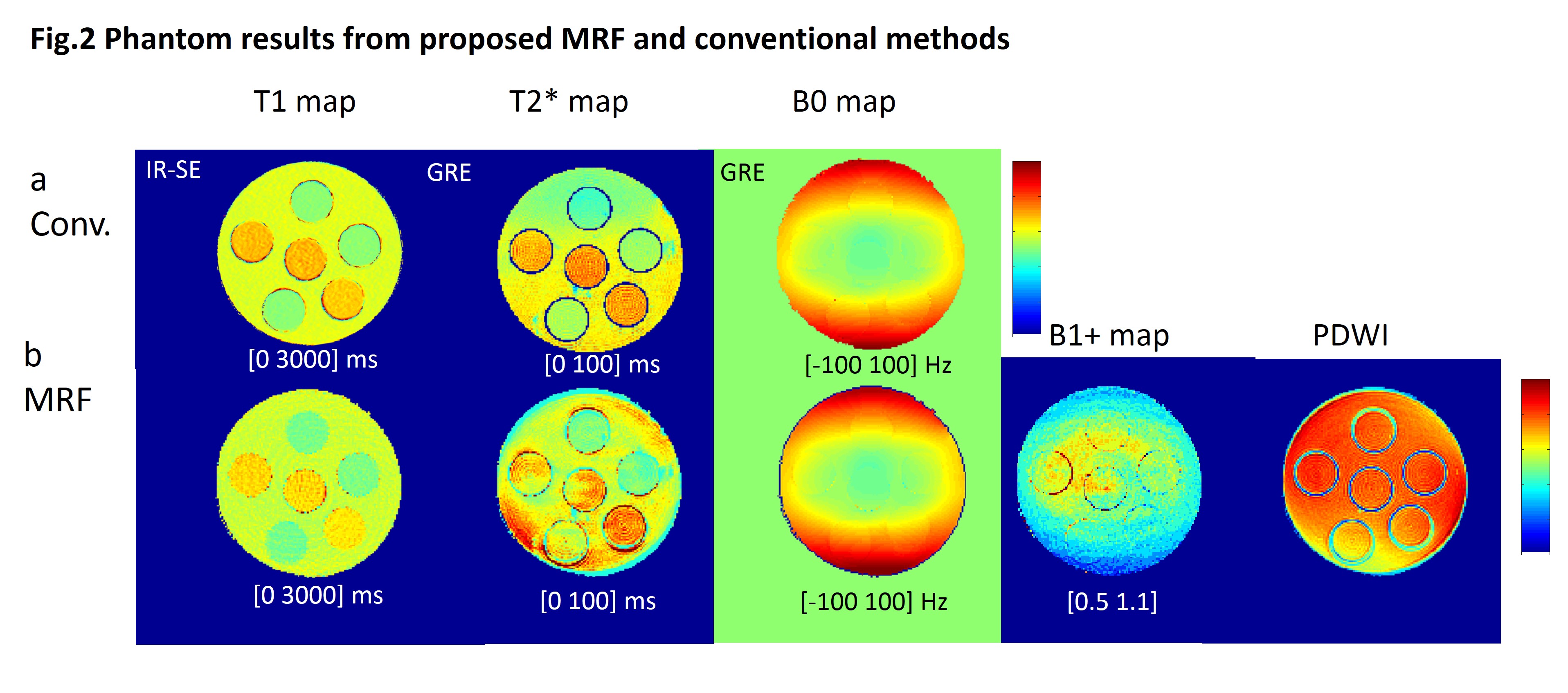
To validate the feasibility of B1+ and B0 detection, experiments were conducted on both a phantom and in vivo brain on a 3T Siemens Prisma scanner. For both scan, short TR was chosen at minimal of 12ms and long TR was chosen at 48ms to accommodate the four spiral readouts, and acquisition time was 12s/slice. For comparison, gold standard T1 mapping with IR-SE sequence at various TIs was obtained on the phantom. T2* map and B0 map were also obtained from a multi-echo 2D GRE scan for comparison.
Bloch equation was used to calculate the dictionary, where three different parameters including T1, T2* and B1+ scaling factor are input. The data was first reconstructed with NUFFT operator, coil combination and then the coarse images were phase corrected with the phase information from the average phase signal from different TEs. The phase information was further phase unwrapped and translated to B0 information. After phase correction, the image frames were matched to the precalculated dictionary pixel-by-pixel to retrieve the parameter values. Finally, the PD weighted image (PDWI) was calculated from the matching coefficients x normalized value of signal frame / normalized value of corresponding dictionary element.
Results
Fig.2 shows the phantom result from both conventional methods and the proposed MRF method. Upper row shows the conventional T1, T2* and B0 mapping results. Bottom row shows the MRF results. One can observe that the T1 from MRF matches well with that from gold standard IR-SE method and the MRF B0 map is almost identical to that from the conventional GRE result. B1+ scaling factor map from MRF is of reasonable quality while the T2* map is blurred.
Fig.3 shows the in-vivo brain results from the proposed MRF scheme, one lower brain slice on the left and one upper slice on the right.
Discussions and Conclusions
In this work, we proposed a novel MRF scheme which simultaneously maps B1+ and B0 in addition to T1 and T2*. Both phantom and in vivo scans were conducted to validate the method. B0 map shows good quality and can be used for further calculation such as in QSM and also can be used for spiral image correction. B1+ scaling factor map shows the transmit coil pattern while noisy which is likely due to the low B1+ contrast and low SNR. Potential applications of the method may include human body areas where severe B1+ inhomogeneity and B0 inhomogeneity generally degrade the MRF mapping accuracy.Acknowledgements
This work was supported by the National Natural Science Foundation of China (61701436, 81401473, 91632109), National Key R&D Program of China (2017YFC0909200) and the Fundamental Research Funds for the Central Universities (2017QNA5016).References
1. Ma D, Gulani V, Seiberlich N, Liu K, Sunshine JL, Duerk JL, Griswold MA. Magnetic resonance fingerprinting. Nature 2013;495:187–192. doi: 10.1038/nature11971.
2. Buonincontri G, Sawiak S. MR fingerprinting with simultaneous B1 estimation. Magn Reson Med 2016;76:1127–1135. doi: 10.1002/mrm.26009.
3. Cloos MA, Knoll F, Zhao T, Block KT, Bruno M, Wiggins GC, Sodickson DK. Multiparametric imaging with heterogeneous radiofrequency fields. Nat. Commun. 2016;7. doi: 10.1038/ncomms12445.
4. Ma D, Coppo S, Chen Y, McGivney DF, Jiang Y, Pahwa S, Gulani V, Griswold MA. Slice profile and B 1 corrections in 2D magnetic resonance fingerprinting. Magn Reson Med 2017;78:1781–1789. doi: 10.1002/mrm.26580.
5. Yarnykh VL. Actual flip-angle imaging in the pulsed steady state: a method for rapid three-dimensional mapping of the transmitted radiofrequency field. Magn Reson Med 2007;57:192–200. doi: 10.1002/mrm.21120.
Figures