0171
Improved multi-band RF performance using GRATER-based predistortion1Biomedical Engineering, University of Southern California, Los Angeles, CA, United States, 2Electrical Engineering, University of Southern California, Los Angeles, CA, United States
Synopsis
The Gradient Reversal Approach to Evaluate RF (GRATER) has been shown to accurately measure small-tip RF pulses in phantoms, without the need for added hardware or sophisticated processing. Imperfect RF production can be measured with GRATER, and RF waveforms can be appropriately predistorted. We demonstrate substantial improvements in multi-band RF performance using this approach. For example, a 0.648 ms, 30º FA, 4- band RF pulse with 2 cm center-to-center spacing and 5 mm slice thickness (desirable for SMS cardiac imaging) excites spurious side-lobes with 10.4% and 3.4% max signal before and after GRATER-based RF predistortion, respectively.
Purpose
RF pulses with high peak B1 and rapid fluctuations in supply current are susceptible to RF amplifier nonlinearity [1,2]. This causes undesirable effects, such excitation of spurious side-lobes with multi-band RF pulses [1]. Imperfections can be reduced with predistortion, however current methods require extra hardware and synchronization [1,3,4]. The Gradient Reversal Approach to Evaluate RF (GRATER) has been shown to accurately measure small-tip RF pulses in phantoms with <1.5% normalized root mean square error (NRMSE) without extra hardware or synchronization [5]. Here, GRATER-based predistortion is shown to improve 4- and 5-band RF pulse performance with optimized phase scheduling [6] and is demonstrated in bSSFP body imaging, which requires moderate flip angles to achieve optimal image contrast and short RF duration to minimize TR and banding artifacts [7].Methods
Experiments were performed on a 3T GE HD23 scanner. GRATER measurements were obtained with the body coil, centered about a 40x10x10 cm3 rectangular phantom. The scanner was loaded with 280 lbs. Collected data was transferred off the scanner, adjusted, predistorted, formatted, and transferred back in <2 minutes. Waveform measurements and their excitation profiles were compared with and without predistortion. 4-band images were obtained with similar scanner loading in phantoms and in-vivo with and without predistortion.
RF pulse design
4- and 5-band RF pulses were designed using the SLR algorithm [8] with 0.648 ms duration, 324 point resolution, 30º flip angle, 2 cm center-to-center spacing, and 5 or 10 mm slice thickness. Optimized phase scheduling was used to minimize peak B1 [6]. Waveforms were implemented as smooth real and corresponding phase components to avoid sharp transitions.
GRATER measurement
Transmit and sampling period were 2μs. The readout gradient amplitude was halved and its duration doubled compared to the slice-select gradient to measure 648 waveform points. GRATER data was copied to a local computer and adjusted; 1) Preprocessing: GRATER measurements were scaled so their maximum values matched the programmed waveform, decimated by a factor of 2, and the conjugate was taken. 2) Processing: The waveform was adjusted according to estimated parameters from the solution of a bounded minimum-norm least squares optimization problem [5]: amplitude A, transverse-relaxation T2*, off-resonance Δf, initial phase angle Φ, and time-shift t0. 3) Post-processing: The waveform was separated into real and phase components to match waveforms in the above sub-section.
Predistorted RF pulse design
The predistorted waveform was created by taking 2 times reference minus processed GRATER waveforms. The phase waveform was then updated as a time-shifted version of the original waveform, shifted to minimize error between itself and predistorted phase.
RF pulse evaluation
Metrics were compared with and without GRATER-based predistortion. NRMSE was compared between desired and measured waveforms. With the same setup as for GRATER measurements, z-profile measurements were made by moving the readout to the slice-select axis of a bSSFP imaging sequence (TR = 3.2 ms, TE = 1.5 ms) using the 4-band RF pulse. Maximum side-lobe signal and mean signal of the largest side-lobe were calculated in z-profiles.
Application: bSSFP cardiac imaging
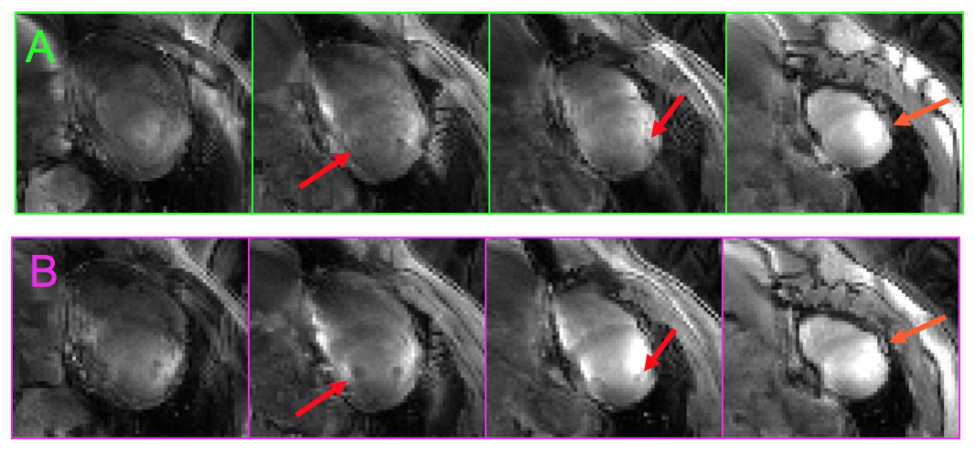
An 8-channel cardiac coil was used with the same scanner loading as previous experiments. To prevent undersampling artifacts, 4-band fully-sampled bSSFP imaging was performed using blipped-CAIPI encoding [9], with and without GRATER-based predistortion. A lego phantom with a different pattern every 2 cm deep was submerged in water and imaged to emphasize aliased signal from extra excited slices. In-vivo images were obtained with Institutional Review Board approval in the short-axis slice of the heart of a healthy volunteer (M, 23 years, 200 lbs) with 80 lbs of additional loading.
Results
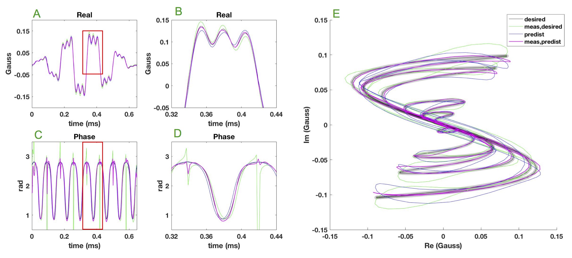
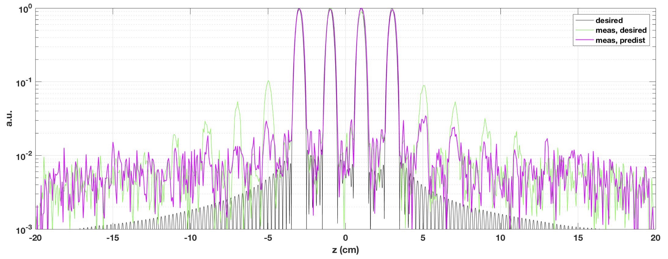
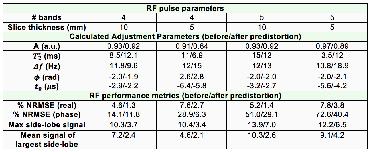
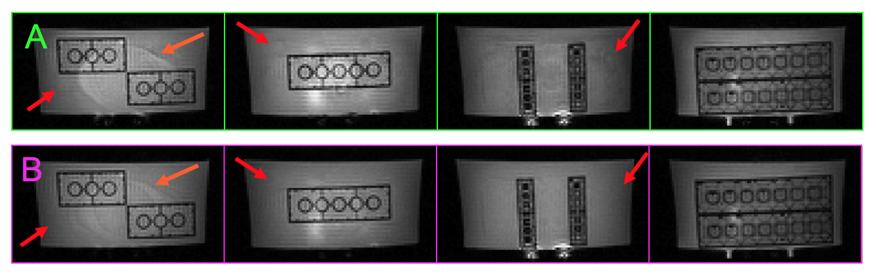
With and without predistortion, Figure 1 demonstrates the real and phase components of the desired and measured 4-band pulse with 5 mm thick slices and Figure 2 shows the z-profile. Table 2 summarizes the adjustment parameters and RF pulse evaluation metrics for the pulses in this study. With and without predistortion, reconstructed slices of fully sampled 4-band/5 mm-thick bSSFP imaging are shown in the lego phantom (Figure 3) and in-vivo (Figure 4).Conclusions
GRATER-based predistortion reduces multi-band envelope error and improves the quality of SMS reconstructed images. The demonstrated 0.648 ms RF pulses are appropriate for SMS cardiac bSSFP imaging, where scan times, including RF duration, are kept short to minimize physiological noise and a moderate flip angle is desirable. Future work will include implementation of fast, on-the-scanner GRATER-based predistortion and exploration of iterative methods to further improve RF transmit accuracy and SMS bSSFP body imaging.Acknowledgements
National Institutes of Health #R01-HL130494References
[1] Zhu K et. al., RF Amplifier Nonlinearity Correction for Multiband RF pulses, 23rd ISMRM; p. 3763, 2015
[2] Chan F et. al., Effects of RF amplifier distortion on selective excitation and their correction by prewarping, Magn Res Med, Vol 23; p. 224-238, 1992
[3] Zanchi M et. al., Frequency Offset Cartesian Feedback Control System for MRI Power Amplifier Linearization, IEEE Med Img, Vol 30; p. 512-522, 2011
[4] Stang P et. al., Vector Iterative Predistortion: An auto-Calibration Method for Transmit Arrays, 17th ISMRM; p.395, 2009
[5] Landes V and Nayak K, Simple method for RF pulse measurement using gradient reversal, Magn Reson Med, doi:10.1002/mrm.26920, 2017
[6] Wong E, Optimized Phase Schedules for Minimizing Peak RF Power in Simultaneous Multi-Slice RF Excitation Pulses, 20th ISMRM; p. 2209, 2012
[7] Hargreaves B, Fast Gradient Echo Sequences Including Balanced SSFP, J Magn Reson Imaging. Vol 20; p. 857–864, 2004
[8] Cunningham C and Wood M, Method for improved multiband excitation profiles using the Shinnar-Le Roux transform, Magn Reson Med, Vol 42; p. 577-584, 1999
[9] Setsompop K et. al. Blipped-controlled aliasing in parallel imaging for simultaneous multislice echo planar imaging with reduced g-factor penalty. Magn Reson Med, Vol 67; p. 1210-1224, 2012
Figures