0145
Higher and more homogeneous B$$$_1^+$$$ for bilateral breast imaging at 7T using a multi-transmit setup with 5 dipole antennas and a 30-loop element receive array1Radiology, UMC Utrecht, Utrecht, Netherlands, 2Biomedical Image Analysis, Eindhoven University of Technology, Eindhoven, Netherlands
Synopsis
Imaging of the breast at 7 tesla is compromised by the inhomogeneous B1+. To overcome this challenge we explored the use of five fractionated dipole antennas in a multi-transmit system in combination with 30 receiver coils. This coil shows larger SNR, larger FOV and higher and more homogeneous B1 field in the breasts than the currently used breast coil at our institute. The high B1+ and an increased field of view achieved by the fractionated dipole antennas, opens the way to translate routinely used breast imaging protocols from 3T to 7T enabling advanced clinical research.
Introduction
Imaging of the breast at 7 tesla (7T) is of interest due to the increased spectral and spatial resolution enabling characterization of breast cancer and monitoring of treatment (1,2). However, breast imaging at 7T is challenging due to severe non-uniformities in RF transmit fields. Particularly MR sequences sensitive to B1+ field uniformity (e.g. turbo spin echo; TSE) can still not compete to the clinical standard at 3T. This hampers clinical research at 7T as the 7T exam cannot replace the clinical 3T standard yet. A wide variety of breast MRI studies at 7T have been presented with various RF coil setups, from unilateral two-channel transmit/receive setup, to bilateral and combined with 26 receive channels (3,4). Although imaging performance in the anterior part of the breast is generally good, clinical usability is impeded by a drop of signal towards the major pectoral muscle due to the B1 inhomogeneity and limited penetration depth. In this study we explored the use of five fractionated dipole antennas (5) to improve the transmit efficiency and penetration depth compared to the previously developed two-channel transmit with a 26-channel receive setup (4).Subjects and methods
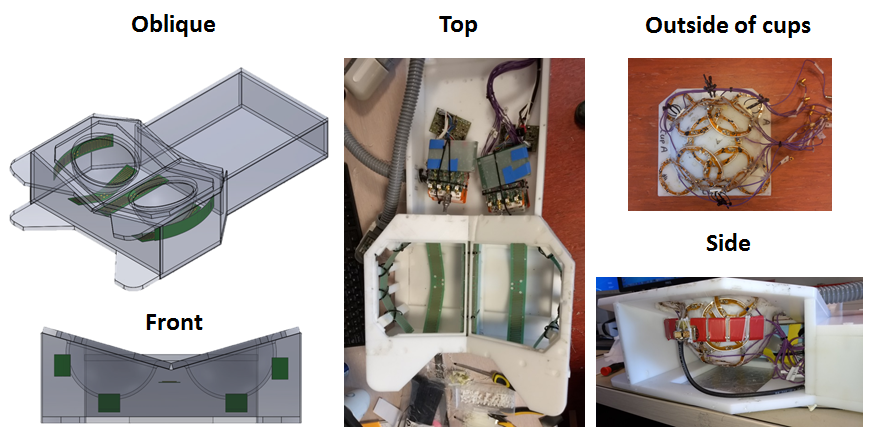
Setup - Five fractionated dipole antennas connected to five transmit channels of an eight channel multi-transmit setup were used on a 7T MR system (Philips, Cleveland, OH, USA). Each dipole antenna was driven at 800W input power; the position of the antennas is shown in Figure 1. 30 detunable receiver coils were positioned around the breast and interfaced, via integrated preamps, to the system’s receiver chain. Coupling between antennas and from antennas to detuned receiver loops was evaluated.
Simulation - Finite difference time domain simulations (Sim4Life, Zurich Med Tech, Zurich) were performed to evaluate transmit efficiency and RF safety limits of the setup. SAR distributions were simulated on an adjusted human model of Ella of the virtual family (6) where the breasts are replaced by a breast model generated from Dixon scans to better correspond to the breast shape in prone position.
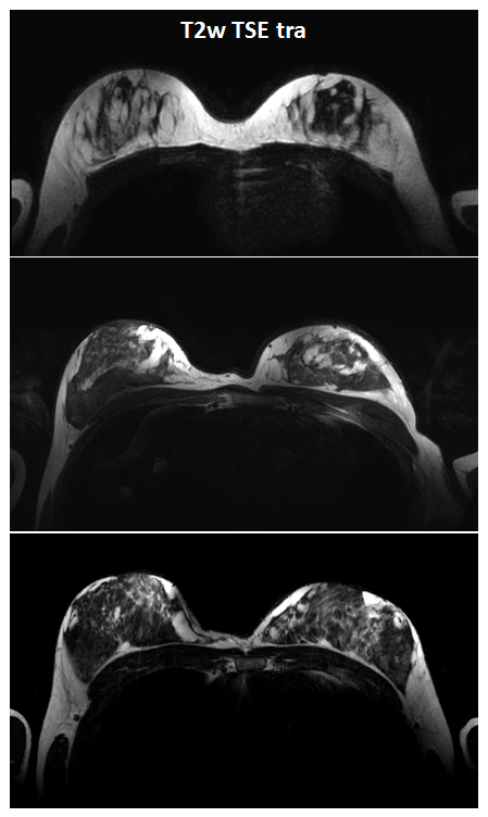
Testing –After informed consent, three healthy female volunteers were scanned. A B1 map (AFI, TR1=150ms; TR2=650ms; TE=2.4ms; FA=65⁰; resolution=3.9x3.8x10mm3), T1-weighted image (FFE, TR=70ms, TE=20ms, FA=15⁰, SENSE=1, resolution=1x1x5mm3) and a T2w TSE image (TR=10000ms; TE=90ms; FA=90⁰; resolution=0.7x0.7x3mm3, TSE factor=17) were acquired after B1 shimming. To measure the signal to noise ratio (SNR), the T1w images were reconstructed in SNRunits (7,8).
Comparison with currently used coil – The g-factor maps, SNR and B1+ performance of the breast coil with dipole antennas was compared to the performance of the currently used breast coil at 7T at our institute consisting of two quadrature driven transmit loop pairs combined with 26 receive loops around the breasts connected to the conventional dual-transmit system.
Results
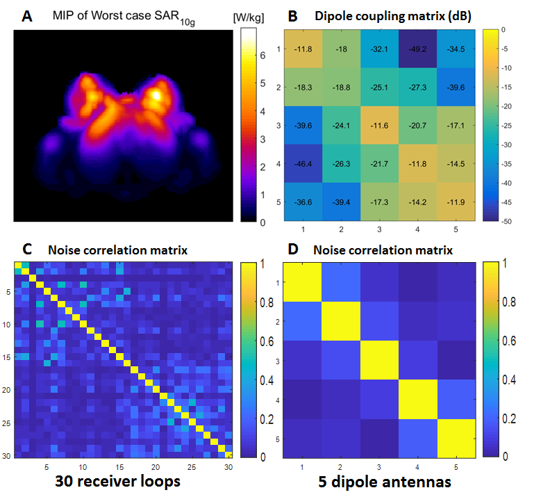
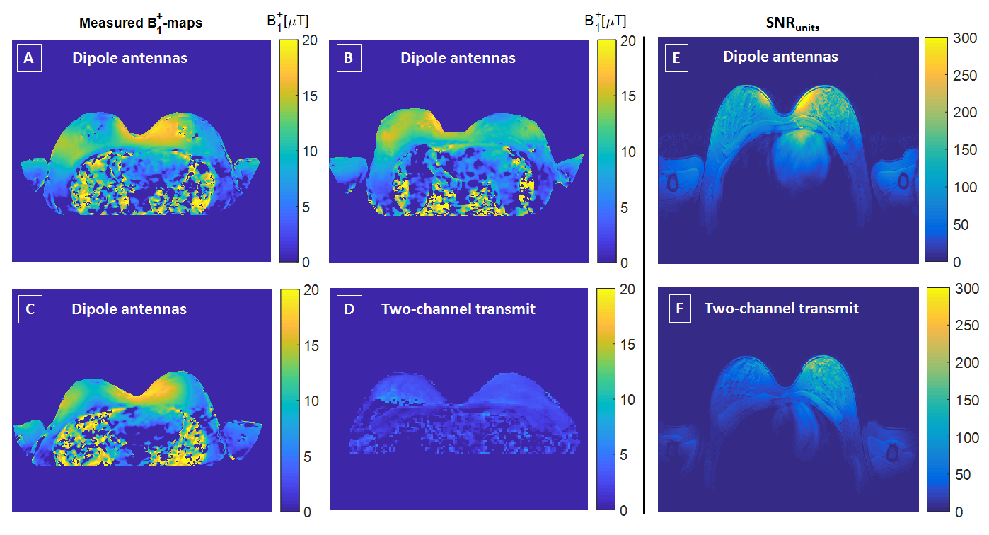
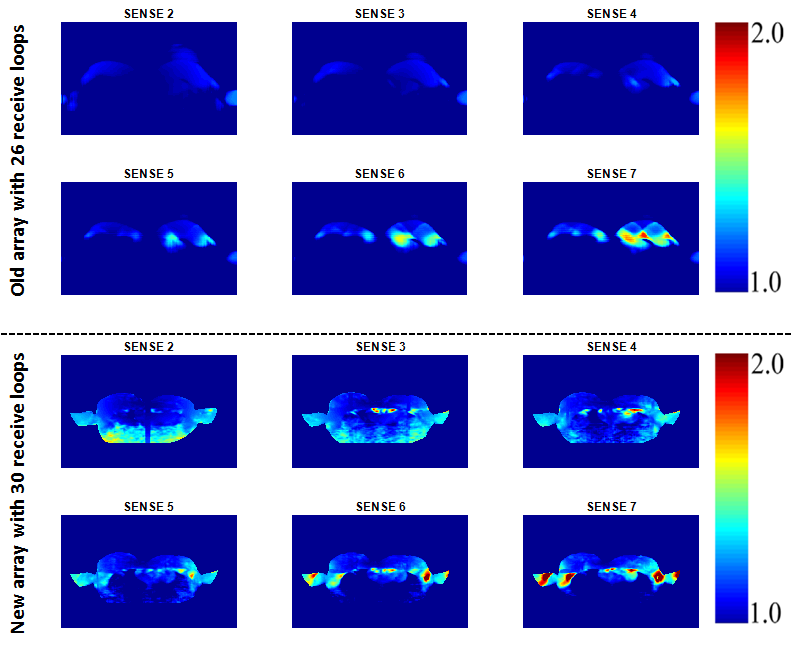
The maximum achievable local SAR value (worst case phase settings, 5x1 W accepted power) is 7.0 W/kg (Figure 2A). If we allow a maximum SAR of 20 W/kg, an average power of 2.86 W/channel can be used. Maximum inter-element coupling of the transmit dipole array was -14.2 dB while maximum reflection was -11.6 dB (Figure 2B). The noise correlation matrix (Figure 2C and 2D) shows a maximum value of 0.50 for the 30 receive loops and 0.23 for the 5 dipole antennas. An average B1+ value of 12 μT is achieved throughout the breasts in three volunteers (Figure 3A, B and C). The coil with the dipole antennas shows a higher SNR compared to the currently used breast coil for dual-transmit, especially in the right breast (Figure 3E and F). Comparison of the g-factor maps is presented in Figure 4. The high B1+ in the breast enabled good quality T2w TSE images (Figure 5).Discussion and conclusion
Using the multi-transmit system and the fractionated dipole antennas, we were able to achieve a high (12 μT) B1+ compared to the two-channel transmit setup in the breast (5 μT). The g-factor maps of the dipole antennas show overall higher values compared to the other coil, however, if we only look at the breasts, the maps are comparable or even slightly better with the new array. Moreover, the SNR and the penetration depth of the coil are much larger than before. The breast coil with five fractionated dipole antennas can generate a higher B1+ over a larger FOV in the breasts at 7T compared to breast coils presented so far. This opens the way to translate routinely used breast imaging protocols from 3T to 7T, whilst benefitting from the high spectral and spatial resolution at 7T in clinical research at 7T.Acknowledgements
No acknowledgement found.References
1. Stehouwer BL, Klomp DWJ, van den Bosch M a a J, et al. Dynamic contrast-enhanced and ultra-high-resolution breast MRI at 7.0 Tesla. Eur Radiol. 2013;23(11):2961–2968http://www.ncbi.nlm.nih.gov/pubmed/23982289. Accessed October 23, 2014.
2. Stehouwer BL, Klomp DWJ, Korteweg M a, et al. 7 T versus 3T contrast-enhanced breast magnetic resonance imaging of invasive ductulolobular carcinoma: first clinical experience. Magn Reson Imaging. Elsevier Inc.; 2013;31(4):613–617http://www.ncbi.nlm.nih.gov/pubmed/23116848. Accessed October 23, 2014.
3. Italiaander M, Nijholt PJ, Kraff O, et al. High B1 dutycycle in bilateral breast imaging at 7T. Proc Intl Soc Mag Reson Med 20. 2012;20:2012.
4. Van Der Velden TA, Italiaander M, Van Der Kemp WJM, et al. Radiofrequency configuration to facilitate bilateral breast 31P MR spectroscopic imaging and high-resolution MRI at 7 Tesla. Magn Reson Med. 2015;74(6):1803–1810.
5. Raaijmakers AJE, Italiaander M, Voogt IJ, et al. The fractionated dipole antenna: A new antenna for body imaging at 7 Tesla. Magn Reson Med. 2016;75(3):1366–1374.
6. Christ A, Kainz W, Hahn EG, et al. The Virtual Family--development of surface-based anatomical models of two adults and two children for dosimetric simulations. Phys Med Biol. 2010;55(2):N23–N38.
7. Kellman P, Mcveigh ER. Image reconstruction in SNR units: A general method for SNR measurement. Magn Reson Med. 2005;54(6):1439–1447.
8. Kellman P. Erratum to Kellman P, McVeigh ER. Image reconstruction in SNR units: a general method for SNR measurement. Magn Reson Med. 2007;58:211–212http://doi.wiley.com/10.1002/mrm.21261.
Figures