0144
A 16-channel Rx-only radiofrequency coil for MR spine imaging at 7T1Erwin L. Hahn Institute for Magnetic Resonance Imaging, University of Duisburg-Essen, Essen, Germany, 2High-Field and Hybrid MR Imaging, University Hospital Essen, Essen, Germany, 3Hamm-Lippstadt University of Applied Sciences, Hamm, Germany, 4University of Applied Science Ruhr West, Mülheim an der Ruhr, Germany, 5Medical Physics in Radiology, German Cancer Research Center (DKFZ), Heidelberg, Germany
Synopsis
In clinical MRI systems operating at 1.5 and 3T, built-in 1-channel radiofrequency (RF) transmit body coils are broadly used in conjunction with local receive RF coils. Recently, a 32-channel Tx/Rx remote body coil has been presented for 7T body MRI. In this work we present an additional 16-channel receive-only spine coil to boost signal-to-noise ratio in comparison to measurements where only the 32-channel Tx/Rx remote body coil is used for reception. The SNR gain is demonstrated in a body-sized phantom. Furthermore, first in-vivo imaging results for 7T MRI of the spine during free-breathing are shown.
Introduction
In clinical MRI systems operating at 1.5 and 3T, built-in 1-channel RF transmit body coils are broadly used. For 7T MRI, a 32-channel RF transmit-receive (Tx/Rx) built-in body coil was recently introduced1. In order to further improve the signal-to-noise ratio (SNR) of the 32-channel body coil setup, in this work we present a 16-channel Rx-only RF coil array for 7T MRI of the spine which so far has only been investigated using local Tx/Rx coils2,3.Methods
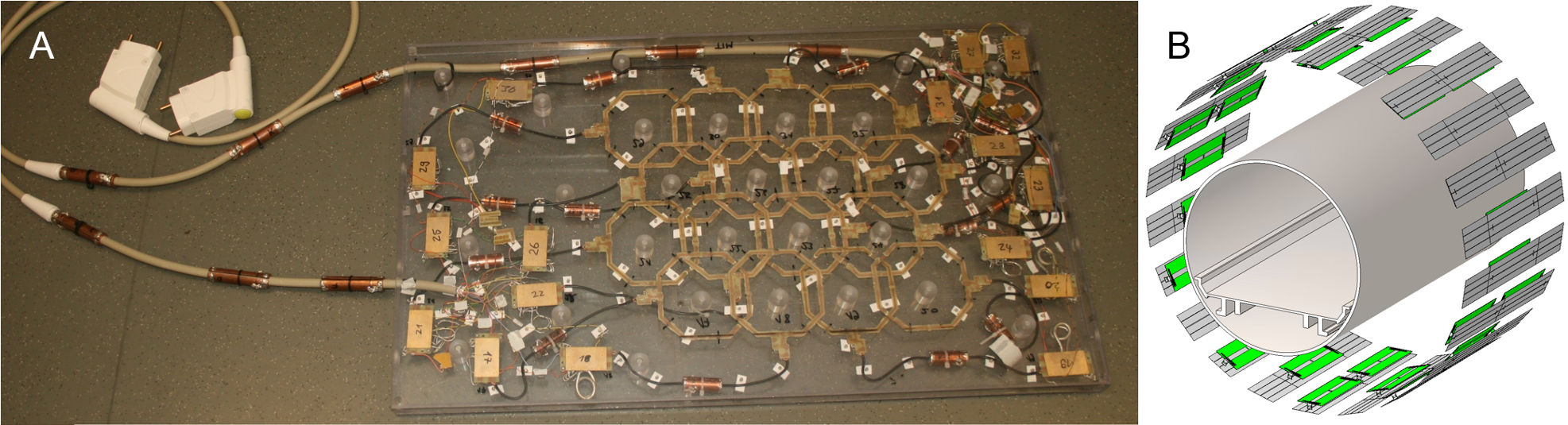
The loop elements and preamplifier boards used for the 16-channel Rx-only spine RF coil are based on a previously published design4. Altogether, 16 octagonal loops of 10-cm diameter are combined to form a 16-channel array housed in a 750 x 450 x 20 mm polycarbonate box (Figure 1A) that can be placed on top of the MRI system patient table. Adjacent loops are decoupled by geometric overlap. Near the element’s feeding point, the semi-rigid cables used for connection are wound to form an inductance and together with a capacitance they form cable traps (cable trap type 1). Additional cable traps (bazooka BalUn, cable trap type 2) are located between each element and the preamplifier board. Further cable traps of type 1 are located both at the input and the output of the preamplifier board. The Tim cables (Total imaging matrix, Siemens Healthineers, Erlangen, Germany) that connect the boards to a 7T whole-body MRI system (Magnetom 7T, Siemens Healthineers, Erlangen, Germany) are equipped with several cable traps of type 2 (Figure 1). A PIN diode on the preamplifier board introduces a short to ground during transmit. This short is transformed to a high impedance at one of the capacitors at the coil terminals using cable transformation. An additional PIN diode and an inductance in parallel to the other capacitor increase the detuning efficiency.
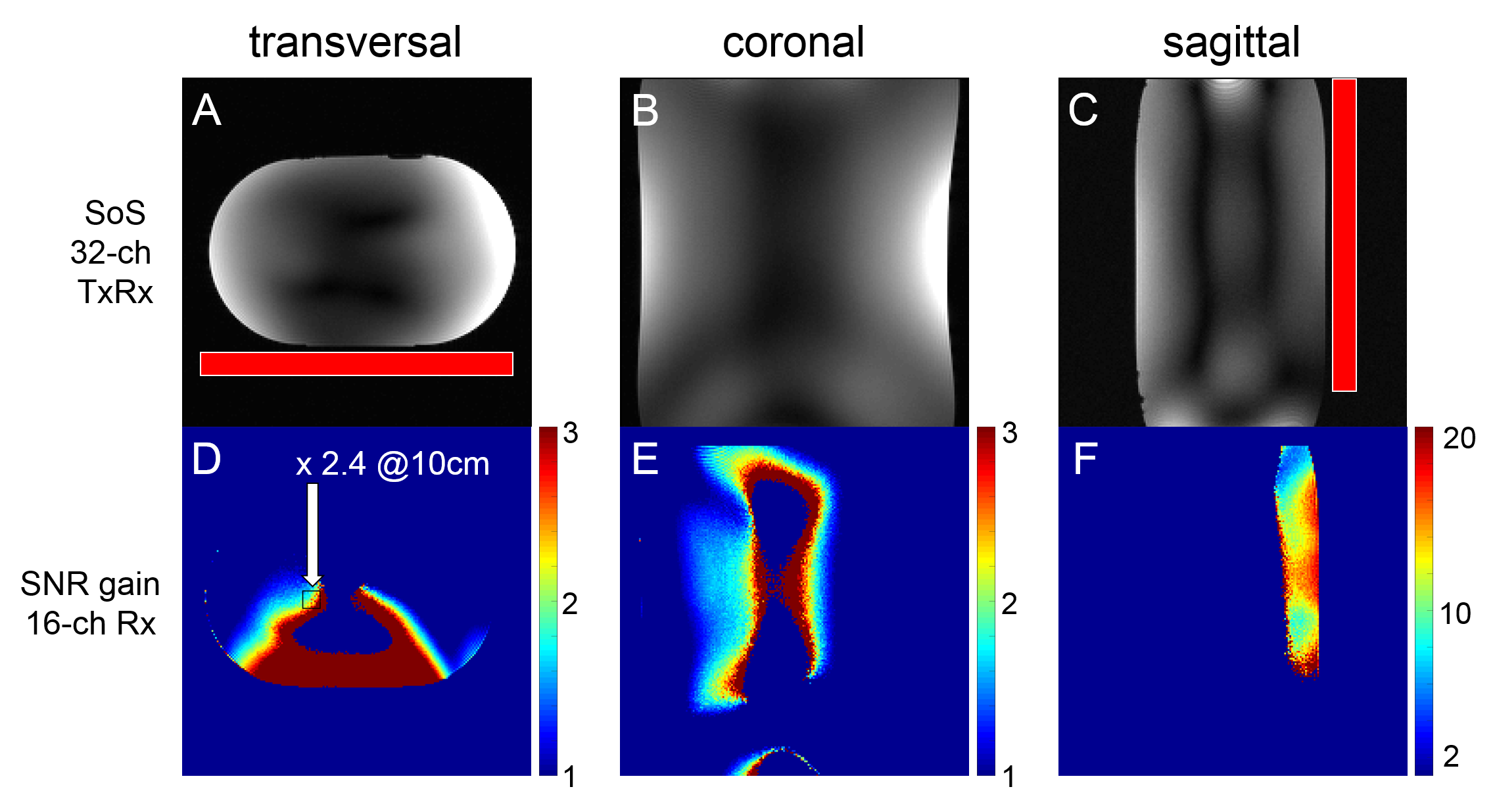
To assess the SNR performance of the 16-channel Rx-only spine coil, measurements in an oval body-sized PVP (Polyvinylpyrrolidone) phantom (32 liters, εr = 45, σ = 0.55Sm-1) were acquired. For transmission, the CP+ mode was used. The SNR gain factor was calculated by dividing SNR maps acquired with the 16-channel Rx-only spine coil by SNR maps acquired with the 32-channel Tx/Rx remote body coil (Figure 1B).
First in-vivo imaging results using a selective pTx excitation during free-breathing were acquired for a male volunteer (35 years old, 190 cm, 85 kg). A FLASH 3D gradient echo sequence was used with a 512 x 128 x 120 matrix, 1 mm3 isotropic resolution, repetition time of TR = 25 ms, echo time of TE = 6 ms, total acquisition time of TA = 6:51 min, pixel bandwidth of 257 Hz/pixel, and a target flip angle of 10°.
Results and Discussion
The results for the SNR evaluation in the body-sized phantom (Figure 2A-C) show distinct SNR boost in all orientations (Figure 2D-F), in particular close to the 16-channel Rx-only spine coil where gain factors in the range of 10-20 can be observed (Figure 2F). Even at 10-cm depth, an average SNR gain factor of 2.4 can be measured in the rectangle in transversal orientation (Figure 2D). As can be seen, signal voids occur due to the CP+ mode, which is not capable of uniformly exciting the entire phantom dimensions in all orientations.
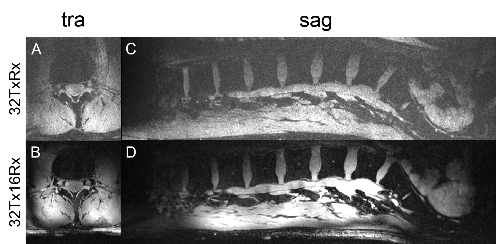
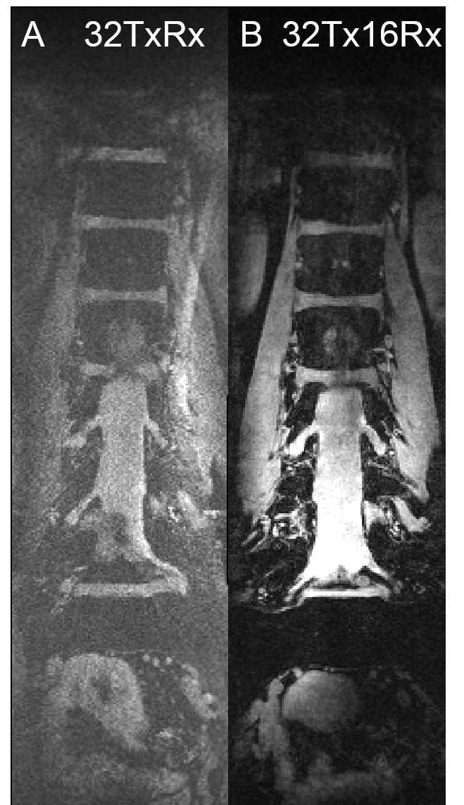
In-vivo imaging results using selective pTx excitation during free-breathing are shown in Figure 3 and Figure 4. The comparison for transversal (Figure 3A,B), sagittal (Figure 3C,D), and coronal (Figure 4A,B) orientation demonstrate how the quantitative SNR boost stated above translates into an improved qualitative image impression. The image noise when using the 16-channel Rx-only spine coil is significantly reduced versus using the 32-channel Tx/Rx body coil for receive, which leads to an improved contrast-to-noise ratio. This is especially prominent for subtle structures close to the 16-channel Rx-only spine coil in Figure 3B, but also in deeper-lying regions such as inside the spine itself (Figure 4B).
Conclusion
It could be shown that the employment of a 16-channel Rx-only spine array yields promising results with respect to SNR and image quality for 7T MRI of the spine. To address 7T MRI in other body parts like the pelvis and abdomen, the presented 16-channel Rx-only setup will be combined with an additional anterior 16-channel receive array in the future.Acknowledgements
The research leading to these results has received funding from the European Research Council under the European Union's Seventh Framework Programme (FP/2007-2013) / ERC Grant Agreement n. 291903 MRexcite.References
1. Orzada et al. A 32-channel integrated body coil for 7 Tesla whole-body imaging. Proc. Intl. Soc. MRM 24, #167 (2016)
2. Wu et al. 7T Human Spine Imaging Arrays With Adjustable Inductive Decoupling. IEEE Trans Biomed Eng 2010;57(2):397–403
3. Duan et al. A 7T Spine Array Based on Electric Dipole Transmitters. Magn Reson Med 2015;74(4):1189–97
4. Rietsch et al. Initial tests of a 4-channel building block for a local 32-channel Rx-only body coil at 7T. Proc. Intl. Soc. MRM 25, #4325 (2017)
Figures