0143
Whole-body 7T 31P birdcage transmit coil driven by a 35kW RF amplifier with an integrated 30-element 31P receive array and an 8-element 1H transmit/receive array1Oxford Centre for Clinical MR Research (OCMR), RDM Cardiovascular Medicine, University of Oxford, Oxford, United Kingdom, 2Department of Imaging Methods, Institute of Measurement Science, Slovak Academy of Sceinces, Bratislava, Slovakia, 3MR Coils BV, Zaltbommel, Netherlands, 4High-Field MR Centre, Center for Medical Physics and Biomedical Engineering, Medical University of Vienna, Vienna, Austria, 5Department of Radiology, University Medical Center Utrecht, Utrecht, Netherlands, 6The Wolfson Brain Imaging Centre, University of Cambridge, Cambridge, United Kingdom
Synopsis
We describe our experiences implementing a whole-body transmit coil driven by a 35kW RF power amplifier, with a 30-element 31P receive array, and an 8-element 1H transmit/receive array, optimised for cardiac 31P-MRS at 7T. We describe an adaptation to the vendor’s standard SAR monitoring to monitor RF power levels up to the full 35kW output of the RFPA. This new hardware was found to achieve better 31P B1+ and SNR at the depth of the heart than other coils available in our institution. This setup promises to allow the first regionally-resolved, whole-heart 31P-MRSI studies at 7T in the near future.
Introduction
31P-MRS plays an important role in the assessment of tissue energy metabolism in vivo, through measurement of high-energy metabolites, e.g. adenosine triphosphate (ATP) and phosphocreatine (PCr). Although cardiac PCr/ATP is a valuable marker of cardiovascular disease1,2, 31P-MRS is not clinically used due to the low SNR and small fields-of-view achievable with clinical MRI scanners and surface coils. SNR can be considerably improved using ultra-high field (7T) scanners, but it remains infeasible to acquire spatially-resolved 31P spectra across the heart using surface transmit coils due to their inhomogeneous field profile. Recently, a whole-body-sized RF birdcage coil for 31P at 7T MR system was shown to generate homogeneous RF excitation for 31P-MRS across the human body3. Furthermore, combining similar whole-body transmit coil with a 16-element receive array further increased SNR for 7T 31P-MRS, enabling cardiac metabolite mapping by 31P-MRSI4. However, these coils were driven by 4kW or 8kW RF power amplifiers (RFPAs)3,4 with correspondingly limited achievable B1+.
We report here initial results from a collaborative project to build and test a whole-body 31P transmit coil driven by a 35kW RFPA and fitted with an integrated 30-element 31P receive array and an 8-element 1H transmit/receive array.
Materials and Methods
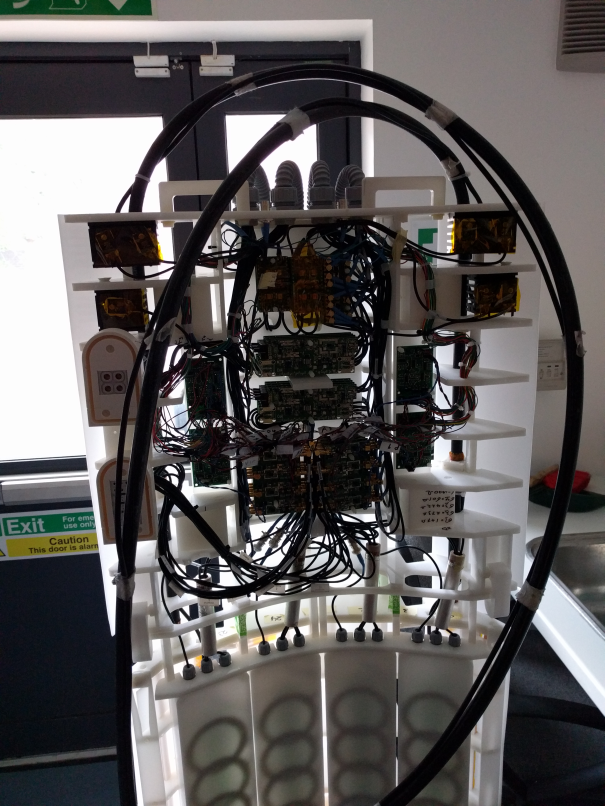
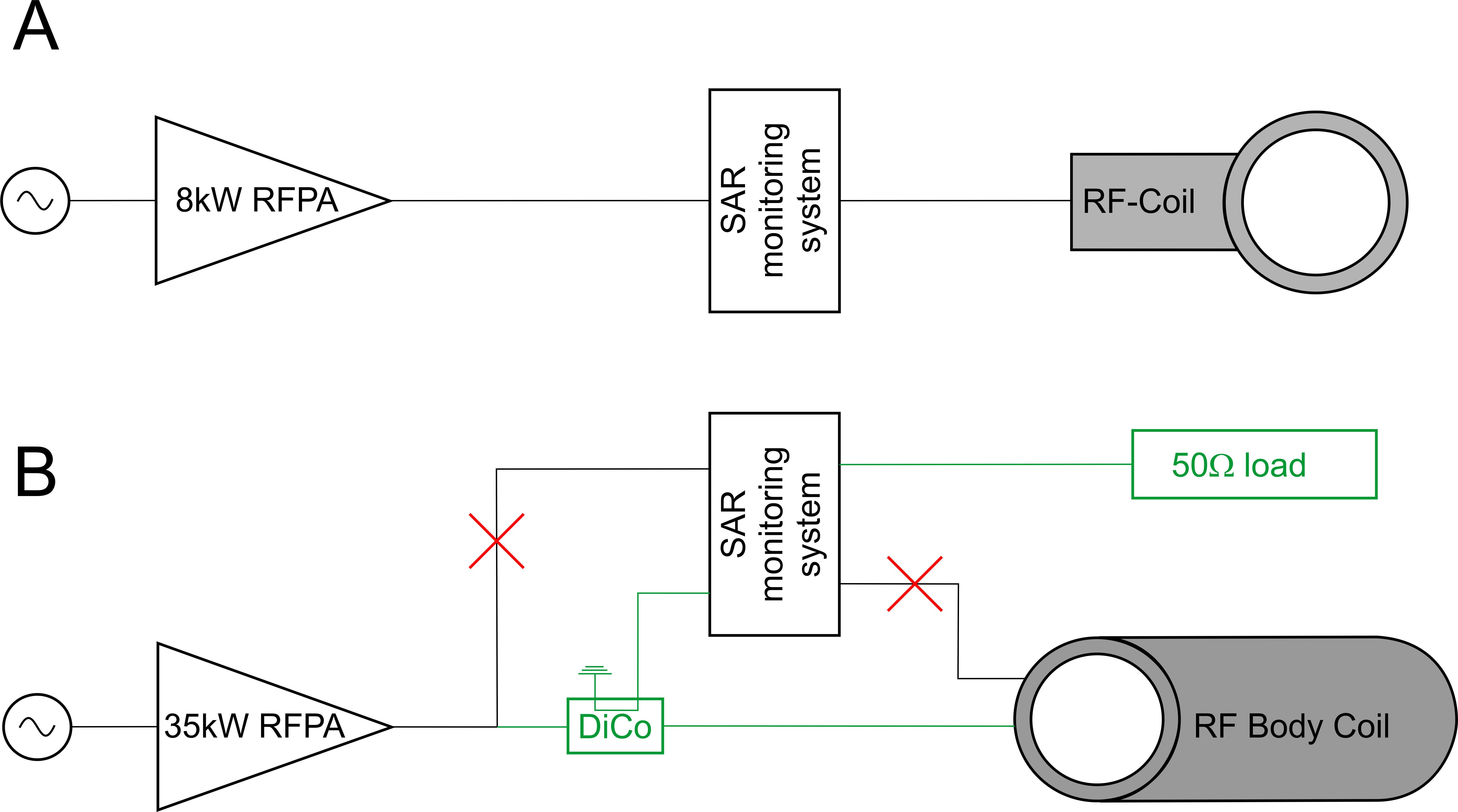
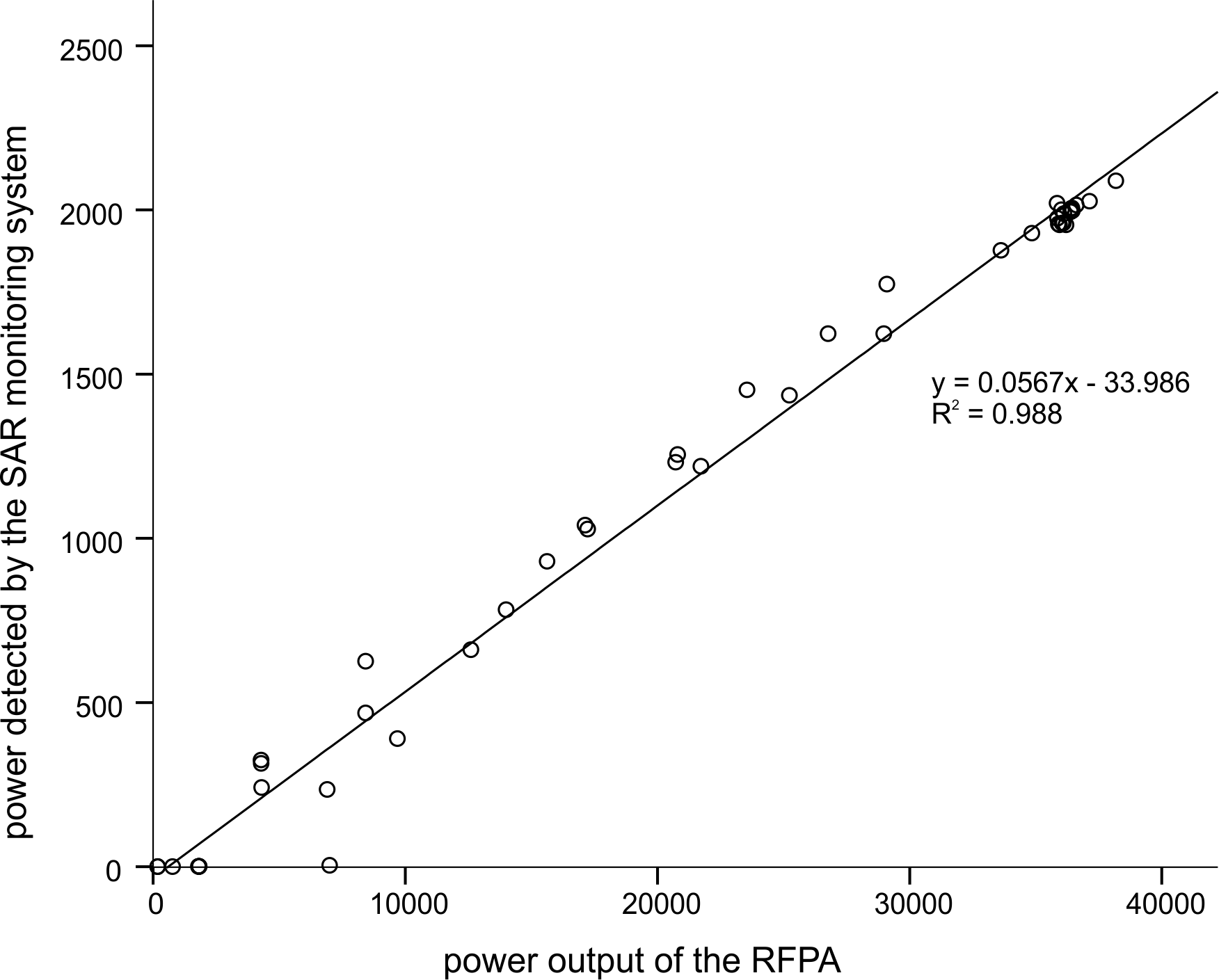
The whole-body coil (manufactured by MR Coils) is built into an extension of the patient table. This rests on custom-built support placed at the service end of the MR scanner4. The table extension was extended further (Figure 1) to accommodate additional electronics: receiver pre-amplifiers, transmit/receive switches, receive-line multiplexers, and an 8-way power divider. The integrated 30ch 31P receive array comprises 16 anterior and 14 posterior loops, 88mm diameter. The 8-element proton transceiver array comprises fractional dipole antennas5. The coil was driven by a MKS-S41 RFPA (MKS Inc, China) operating at 120.3MHz (the 31P resonance frequency in a Magnetom 7T MRI scanner (Siemens)).The scanner’s built-in SAR monitor is only specified for up to 10kW peak power. We therefore constructed a high-power directional coupler to extract a fixed small fraction of the forward power and feed it to the scanner’s built-in SAR monitor and thence into a 50Ω load (Figure 2). This power monitoring design was tested by increasing the system’s modulator output from “0V” to “650V” in “50V” steps and comparing the power output by the RFPA (reported through the RFPA’s interface) with the power detected by the scanner’s built-in SAR monitor.
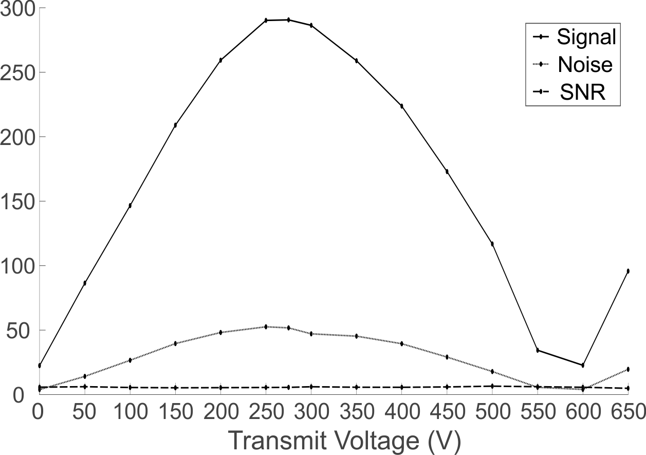
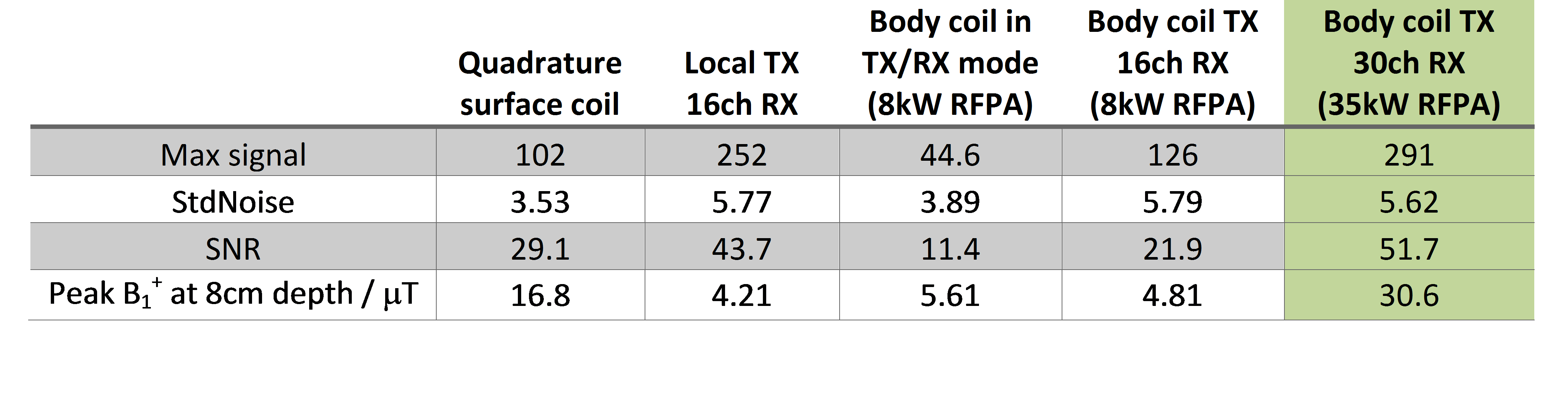
The performance of the coil was tested in a two compartment phantom consisting of a 14L container filled with 18mM saline and a 2x2x2cm3 cube, filled with 1.8M KH2PO4(aq), positioned 8cm above the patient table surface. Fully relaxed non-localized FIDs (1ms rectangular pulse, TR=10s) were acquired for modulator outputs from “0V” to “650V”. The Peak B1+ and SNR were quantified from the WSVD6 combined acquisition with the highest signal amplitude (i.e. a 90° pulse). These were compared to previously measured values using a quadrature surface coil7, 16ch receive array with a local transmit loop (Rapid Biomedical), whole-body coil in transceiver mode, and a combination of whole-body transmission and 16ch reception4.
Results and Discussion
Figure 3 depicts the calibration measurement of the SAR monitoring system. Strong linear correlation can be seen, showing good calibration of the SAR monitoring system using only fraction, i.e. 6% (corresponding to -12.5dB), of the output of the RFPA. Therefore, scaling of the system’s “k-factor” will allow the proper IEC SAR limits to be monitored by the scanner.The B1+ calibration curve is depicted in Figure 4. The 35kW RFPA achieved excitation angles >180° using a relatively short pulse (1ms), suggesting high peak B1+. The calculated B1+ for the new whole-body coil powered by the 35kW RFPA was 30.6μT and the achieved SNR using the integrated 30ch receive array was 51.7. The comparison to other coils is given in Table 1. The new setup provides superior performance to all the other coils we have used for cardiac 7T 31P-MRS in our lab. Specifically, we now achieve greater B1+ at the depth of the heart than our previous custom-built quadrature surface coil6, and the SNR from the 30-element receive array is better than previously obtained with an anterior-only 16-element receive array8.
Conclusion
A whole-body transmit 31P coil with integrated 30-element receive array was successfully driven at 35kW. Our customized SAR monitoring system was calibrated over the full output range of the 35kW RFPA. The performance in a phantom for this setup is superior to our previously tested coils with the Siemens 8kW RFPA. These results suggest that this system setup will soon enable regionally resolved, whole-heart cardiac 31P-MRSI to be performed for the first time at 7T.Acknowledgements
Funded by a Sir Henry Dale Fellowship from the Wellcome Trust and the Royal Society (098436/Z/12/Z); a Science Enhancement from the Wellcome Trust (Grant No. 098436/Z/12/A); the EPACephalosporin Fund (Grant No. CF 284);the Oxford BHFCentre of Research Excellence (Grant No.RE/13/1/30181); and Slovak Grant Agencies VEGA (2/0001/17) and APVV (15-0029). We gratefully acknowledge support from Iulius Dragonu, Karsten Wicklow and Ulrich Fontius at Siemens Healthcare.References
1. Bottomley P, et al. Radiology 1987;165(3):703-7
2. Neubauer S, et al. Circulation 1997;96(7):2190-6
3. Loring J, et al. NMR Biomed 2016;29(6):709-20
4. Valkovič L, et al. PLoS ONE 2017;12(10):e0187153
5. Raaijmakers AJ, et al. Magn Reson Med 2016;75(3):1366-74
6. Rodgers CT & Robson MD. MagnReson Med 2016;75(2):473-87
7. Schaller B, et al. Proc. ISMRM 2016;24:4006
8. Stoll VM, et al. Radiology 2016;281(2):409-17
Figures