0142
Feasibility Study of a Double Resonant (23Na/1H) 8 Channel Rx Head Coil for MRI at 3T1Computer Assisted Clinical Medicine,Medical Faculty Mannheim, Heidelberg University, Mannheim, Germany
Synopsis
The implementation of 23Na-sodium MRI in the clinical routine is of increasing interest since it can provide valuable information on tissue viability. A design criterion of such double resonant RF setups is to keep the performance of the 1H MRI approximately at the same level as single resonant setups while optimizing the 23Na imaging. This work investigates the feasibility and performance of a double resonant 8 channel receive (Rx) head coil for 1H and 23Na MRI at 3T using EM simulations and a head model.
Introduction
The implementation of 23Na-sodium MRI in the clinical routine is of increasing interest since 23Na MRI can provide valuable information on tissue viability[1]. Since clinical scanners usually do not provide X-nuclei MRI additional hardware has to be used to enable both 23Na and 1H MRI. A design criterion of such double resonant RF setups is to keep the performance of the 1H MRI approximately at the same level as single resonant setups while optimizing the 23Na imaging. In order to increase the receiver sensitivity and enable parallel imaging for 1H MRI multi-coil receiver arrays are the best choice. This work investigates the feasibility and performance of a double resonant 8 channel receive (Rx) head coil for 1H and 23Na MRI at 3T using EM simulations and a head model.Methods
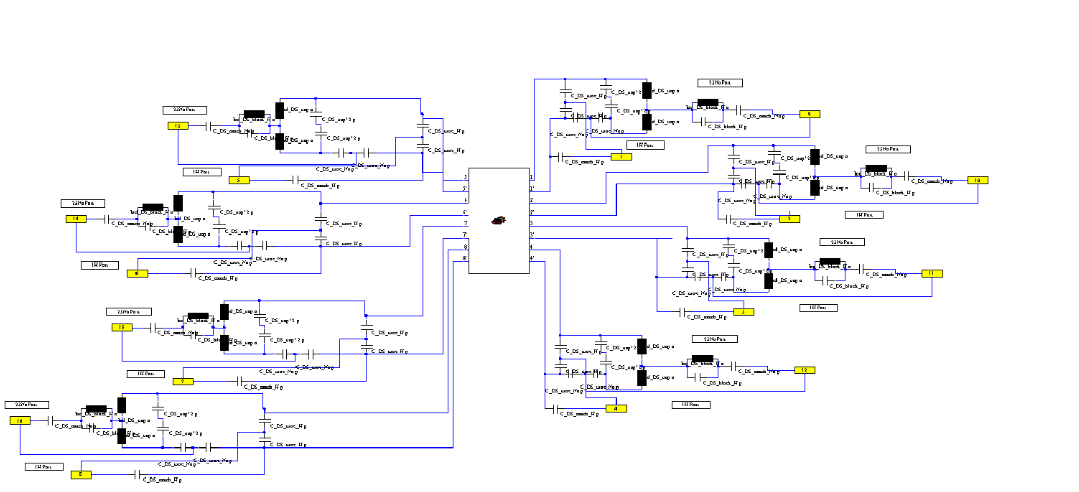
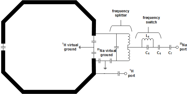
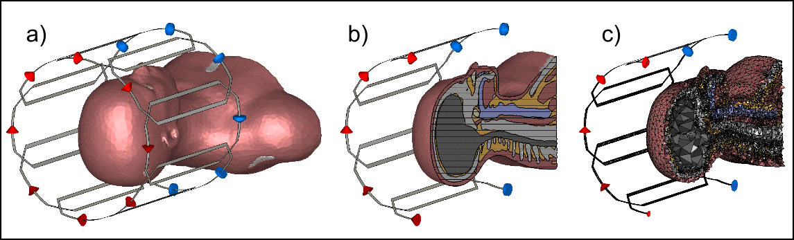
Three different head coils were designed for EM simulations (1H reference coil, 23Na reference coil, 23Na/1H double resonant coil). Each coil (diameter = 260 mm) was comprised of 8 loops (length = 260 mm, width = 134 mm, conductor width = 6 mm, cut twice for lumped elements and ports). The individual loops were decoupled iteratively via overlap. The matching and double resonant circuits were realized using a co-simulation (Figure 1). The double resonant loops were designed using the method introduced in reference[2]. The electrical circuit for a single double resonant loop is plotted in Figure 2. The H-fields of the individual Rx channels were combined using the matched filter approach[3]. All lumped elements were simulated including their equivalent series resistance in order to take the losses of the splitting network into account. A female head model was used as a phantom, which was generated from anatomical surface data using our FEM model processing pipeline[4]. Figure 3 shows the EM simulation setup including the head model. EM fields were calculated using FEM simulations (CST–Computer Simulation Technology GmbH) with a tetrahedral mesh. Mesh refinement converged for all simulations to at least 2% for all S-parameters at the resonance frequencies 32.586 MHz (23Na) and 123.2MHz (1H).Results
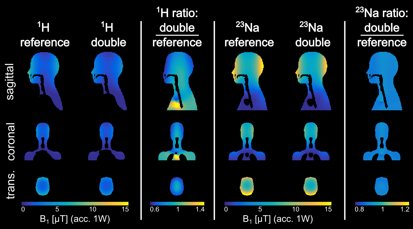
The simulated B1-field (normalized to 1W accepted power) of the reference coils and the double resonant coil are plotted in Figure 4. For 1H the losses of the double resonant coil compared to the reference coil vary from 6% in the center to 35% in the periphery of the head model evaluated in the central transversal plane. However, for 23Na the losses of the double resonant coil differ from 9% in the center to 11% in the periphery evaluated in the same plane as above. The mean B1-field in the center transversal plane drops 25% at the 1H frequency and 11% at the 23Na frequency for the double resonant coil, respectively.Discussion
The double resonant coil showed no artifacts at the 1H and the 23Na frequency, which might have occurred due to the split circuits. The double resonant coil elements were optimized to be most sensitive at the 23Na frequency. Due to this the 1H sensitivity drops more close to the coils compared to the 23Na sensitivity. This might occur due to the optimization for the 23Na frequency as well as due to the overlap which was found to be slightly different for the two frequencies (the perfect overlap for the 23Na frequency was selected). Despite all losses of the double resonant coil compared to the references the drop in B1-sensitivity remained below 10% in the center of the head model.Conclusion
The feasibility of a double resonant 8 channel Rx head coil was proven in simulation on a head model and the performance was compared to reference single tuned coils. Future work should focus on validating the findings in measurements as well as further optimization of the Rx coils, e.g. by splitting them more often.Acknowledgements
No acknowledgement found.References
[1] Madelin G, Ravinder RR. Biomedical applications of sodium MRI in vivo. J Magn Reson Im. 2013;38(3):511-529.
[2] Wetterling F, Högler M, Molkenthin U, et al. The design of a double-tuned two-port surface resonator and its application to in vivo hydrogen-and sodium-MRI. J Magn Reson Im. 2012;217:10-18.
[3] Schnell W, Renz W, Vester M, Ermert H. Ultimate signal-to-noise-ratio of surface and body antennas for magnetic resonance imaging. IEEE T Antenn Propag, 2000;48(3):418-28.
[4] Davids et al., Automatic Generation of Topologically Correct, High Quality, Finite-Element Tetrahedral Body Models from Voxel and Surface Data, ISMRM 2018, Paris
Figures