0140
32-Channel Combined Surface Loop / “Vertical” Loop Tight-Fit Array Provides for Full-Brain Coverage, High Transmit Performance, and SNR Improvement at 9.4T: an Alternative to Surface Loop / Dipole Antenna Combination.Nikolai Avdievich1,2, Ioannis Angelos Giapitzakis2, and Anke Henning1,2
1Institute of Physics, Ernst-Moritz-Arndt University Greifswald, Greifswald, Germany, 2High-Field MR Center, Max Planck Institute for Biological Cybernetics, Tübingen, Germany
Synopsis
Tight-fit human head ultra-high field (UHF,>7T) transceiver (TxRx) surface loop phased arrays improve transmit (Tx)-efficiency in comparison to Tx-only arrays, which are larger to fit receive (Rx)-only arrays inside. A drawback of the TxRx-design is that the number of array elements is restricted by the number of available RF Tx-channels (commonly <16), which limits the Rx-performance. A new 32-element tight-fit human head array, which consists of 18 TxRx-loops and 14 Rx-only vertical loops, was constructed. The array provides for full-brain coverage, ~50% greater B1+, and ~30% greater SNR near the brain center as compared to common Tx-only/ Rx-only (ToRo) array.
Purpose
To improve both the transmit (Tx) and receive (Rx) performance of a human head array and provide for the whole-brain longitudinal coverage at 9.4T, a new 32-element tight-fit array was developed, constructed and tested.Introduction
Tight-fit human head ultra-high field (UHF,>7T) transceiver (TxRx) surface loop phased arrays (1-3) improve transmit (Tx)-efficiency (B1+/√P) in comparison to Tx-only arrays, which are larger to fit multi-channel receive (Rx)-only arrays inside (4). A drawback of the TxRx-design is that the number of array elements is restricted by the number of available RF Tx-channels (commonly<16). This element count is not sufficient for an optimal SNR and parallel Rx-performance. Previously we developed a method of increasing the number of Rx-elements in a TxRx-array without moving Tx-elements further away from the subject, which compromises the Tx-performance. We constructed a 16-element human head array, which consisted of 8 TxRx-surface loops circumscribing a head, and 8 Rx-only “vertical” loops positioned along the central axis of each TxRx-loop perpendicularly to its surface (5). In this work, we extended the new approach by designing and constructing a 9.4T (400MHz) 32-element tight-fit human head array consisting of 18 TxRx surface loops and 14 Rx-only vertical loops with the total number of Rx-elements equal to 32, i.e. the number of available Rx-channels.Methods
The array consists of 18 TxRx surface loops and 14 Rx-only vertical loops with the total number of Rx-elements equal to 32. Fig.1A shows the TxRx-part of the array, i.e. 16 surface loops and two perpendicular vertical loops on the top of the array, both measure 50mm in height. All the loops were constructed of 1.5mm copper wire. In addition, 14 Rx-only vertical loops were placed perpendicularly in the center of each surface loop (Figs.1B and 1C) accept the two surface loops located across the eyes. In the 2nd row the array measures 20cm in width (left-right) and 23cm in height (anterior-posterior). The array length is 17.5cm. To fit a human head, the array was tapered at row 1. Optimized overlapping the surface loops provides for very good decoupling (Fig.2A) without additional decoupling strategies(6). The array is shielded with the cylindrical shield located at 4-cm distance from the coil elements. We compared the performance of the tight-fit array with a larger 16-element Tx-only / 31-element Rx-only (ToRo) surface loop array (28cm - diameter, 19cm - length) described previously for brain studies at 9.4T (4). Electromagnetic (EM) simulations (Figs.2C,D) of the transmit B1+ and the local specific absorption rate (SAR) were performed using CST Studio Suite 2015 (CST, Darmstadt, Germany) and the time-domain solver based on the finite-integration technique (FIT). Three voxel models were used, i.e. a head/shoulder (HS) phantom (4), which was constructed to match tissue properties at 400MHz (ε=58.6, σ=0.64S/m), and two virtual family multi-tissue models, “Duke” and “Ella”. Experimental B1+ maps were obtained using the AFI sequence (7). All data were acquired on a Siemens Magnetom 9.4T human imaging system.Results and Discussion
The tight-fit array provides for a full-brain coverage. It also delivers ~50% greater B1+ averaged over the entire brain than the ToRo-array (Fig.3). Most importantly, it provides for ~30% SNR improvement near the brain center(Fig.4). It is well known that increasing the number of smaller surface loops in a helmet human-head Rx-array only improves peripheral SNR, while SNR near the center practically doesn’t change (8,9). However, when surface and vertical loops are combined, SNR near the center is substantially improved. Both arrays provide for comparable Rx parallel performance (Fig.5). The general idea of our design approach is that the total number of array elements should not exceed the number of available Rx-channels, e.g. 32. During designing, first, the required number of surface TxRx-loops is placed around the object tightly to provide for high Tx-performance. The rest of the loops are used as Rx-only elements, which are positioned to minimize interaction with the TxRx-loops, e.g. vertically between the surface loops and the RF shield (5). In comparison to the common ToRo-design, this method preserves tight fit of the TxRx-loops and, thus, does not compromise the Tx-performance. It also minimizes the total number of array elements and the number of active detuning circuits, which aren’t required for the TxRx-elements.Conclusion
The new approach of constructing the phased array consisting of both TxRx and Rx-only elements simplifies the array construction by minimizing the total number of elements and makes the entire design more robust and, therefore safe. Overall our work provides a recipe for a very Tx- and Rx-efficient design suitable for parallel transmission and reception as well as whole brain imaging at UHF.Acknowledgements
No acknowledgement found.References
1) Avdievich NI, Appl Magn Res 2011;41:483-506. 2) Gilbert KM et al, MRM 2012;67:1487-1496. 3) Avdievich NI et al, NMR in Biomed 2017, 30(2);1-12. 4) Shajan G et al, MRM 71:870-879, 2014. 5) Avdievich NI et al, Proc. ISMRM 25, 2017, 4309. 6) Avdievich NI et al, MRM 2017, DOI:10.1002/mrm.26754. 7)Yarnykh VL. MRM 2007;57:192-200. 8) Wiggins GC et al. Magn Reson Med 2009;62:754-762. 9) Vaidya MV et al. Conc Magn Reson Part B 2014; 44B(3):53-65.Figures
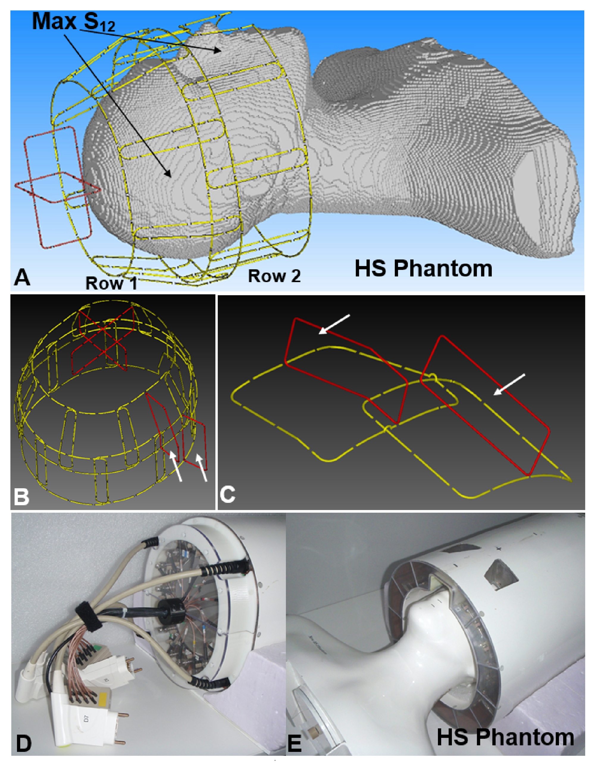
Figure 1. A) CST EM
simulation model of the 18-loop tight-fit TxRx-array loaded by the HS Phantom.
Non-adjacent loops with strongest inductive coupling are shown by arrows. B) EM
simulation model of the TxRx-array with vertical loops shown in red. Marked by
white arrows two Rx-only vertical loops are not present in simulations. They
are shown only as an example of Rx-only vertical loops mounted in the real
array. C) Magnified picture of two exemplary Rx-only vertical loops. D) Photo
of the front side of the phased array. E) Photo of the phased array loaded by
HS phantom.
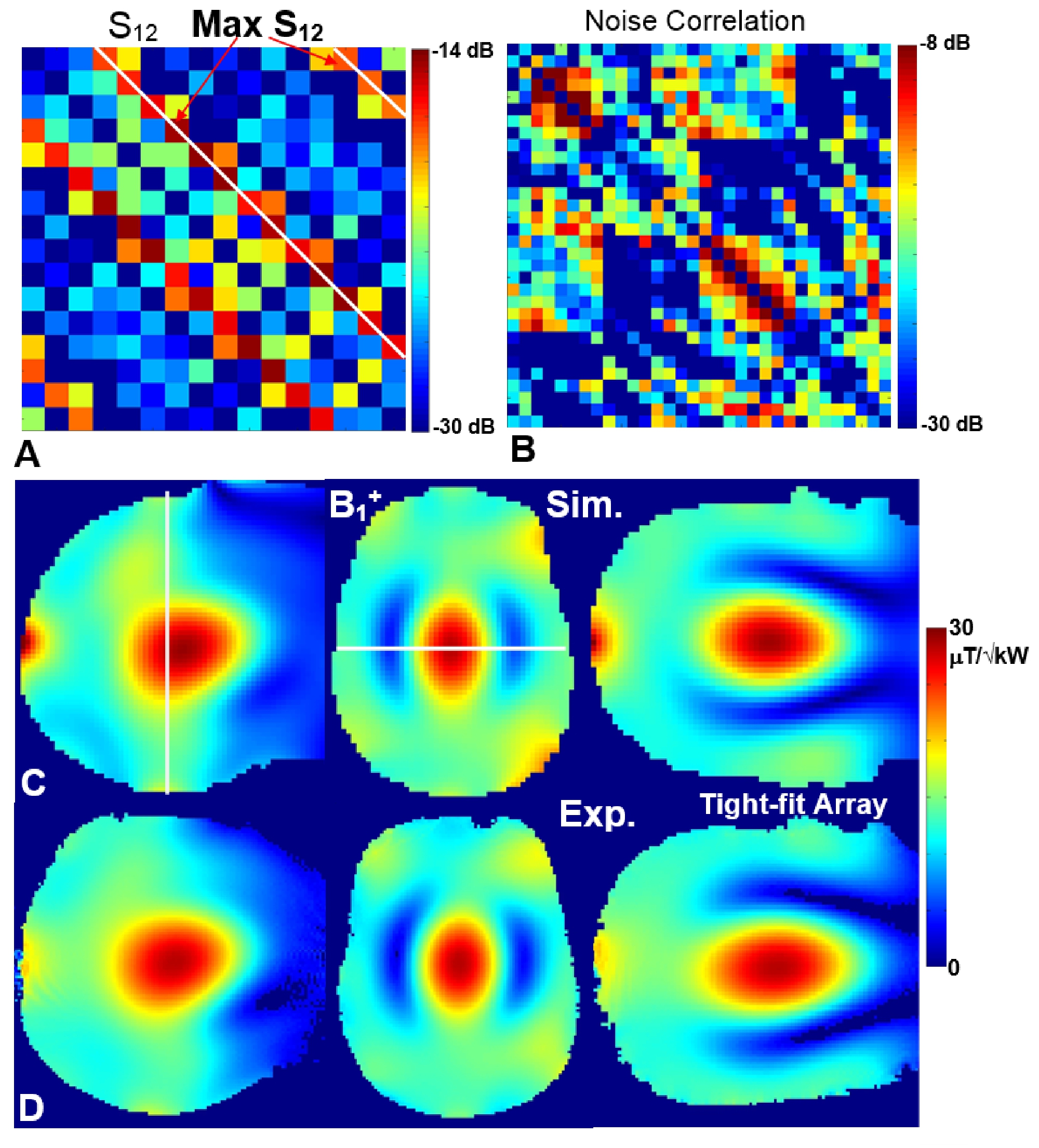
Figure 2. A) S12 matrix
measured for 16 surface TxRx-loops of the tight-fit array loaded by the HS
phantom. B) Noise correlation matrix measured for all 32 loops obtained using
the HS phantom. EM simulated (A) and experimentally
measured (B) central sagittal, transversal, and coronal B1+
maps obtained using the tight-fit array loaded by the HS phantom.
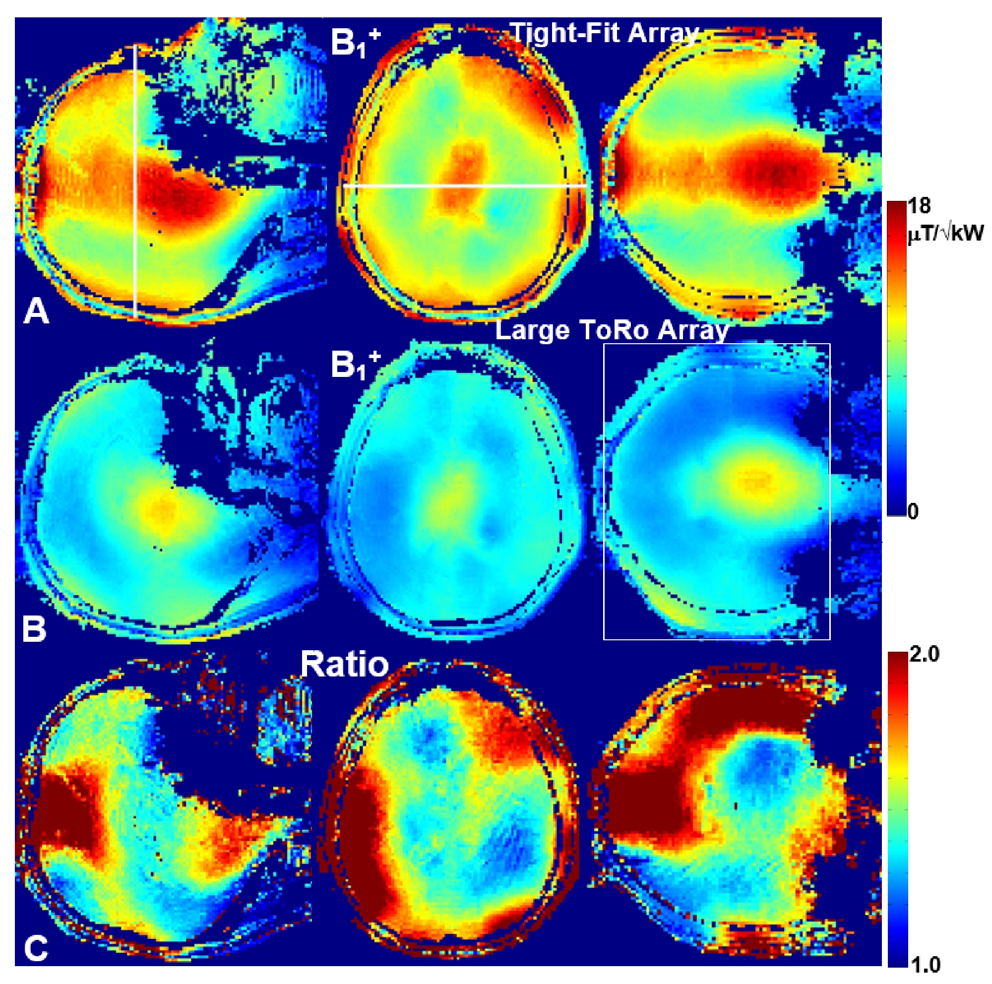
Figure 3. Central sagittal,
transversal, and coronal in-vivo B1+
maps obtained using the tight-fit array (A) and the larger
ToRo-array (B). C) Ratios of the corresponding B1+ maps obtained using the tight-fit array and
the larger ToRo-array (Figs. 3A and 3B). Averaging ROI, i.e. 130-mm transversal
slab is shown in Fig.3B.
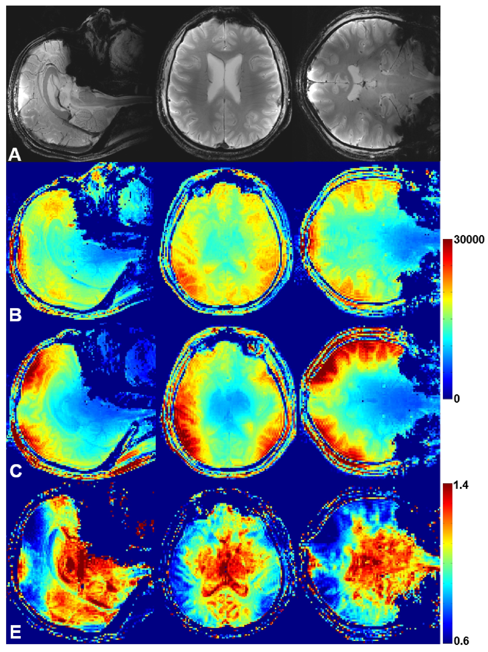
Figure 4. A) Central sagittal, transversal, and coronal
in-vivo human brain GRE images obtained using the tight-fit array. SNR
maps obtained for slices shown in Fig.4A using the tight-fit array (B) and the
larger ToRo-array (C). E) Ratios of the corresponding SNR maps obtained using
the tight-fit array and the larger ToRo-array.
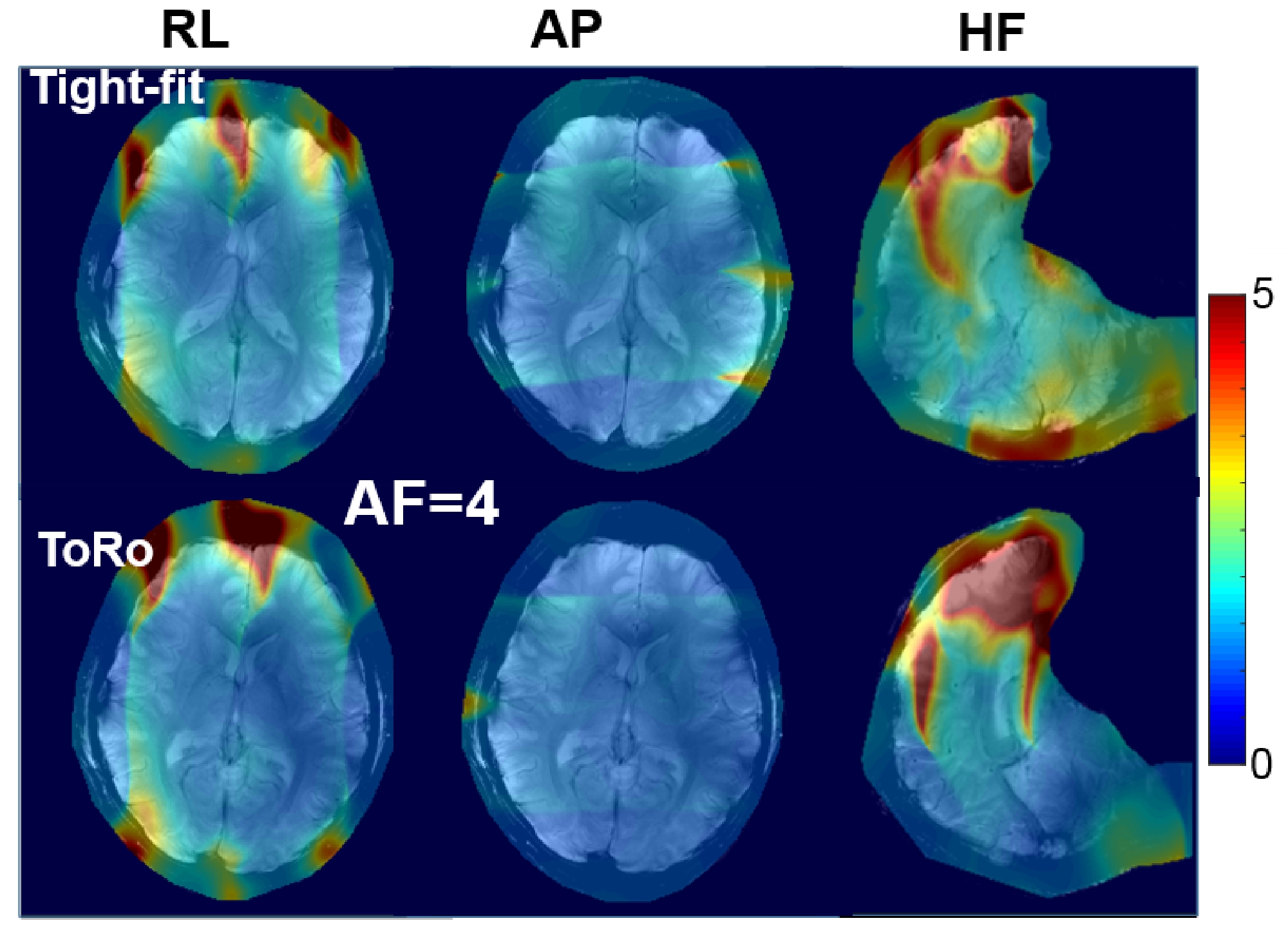
Figure 5. Comparison
of in-vivo g-factor maps of the tight-fit and the ToRo arrays obtained for the
same volunteer and acceleration factor (AF) of 4 in three separate acceleration
directions: right-left (RL), anterior-posterior (AP), and head-foot (HF).