0138
Optimization and validation of dipole antenna geometry for body imaging at 10.5T1Radiology, University Medical Center Utrecht, Utrecht, Netherlands, 2Center for Magnetic Resonance Research, University of Minnesota, Minneapolis, MN, United States, 3Biomedical Image Analysis, Eindhoven University of Technology, Eindhoven, Netherlands
Synopsis
Body MRI at 10.5T shows potential for improving signal-to-noise ratio compared to
Purpose
For body MRI at ultra-high field (UHF, B0≥7T), the use of radiative dipole antennas as surface array elements in a multi-transmit setup is becoming increasingly common1-7. A transmit array consisting of fractionated dipole antennas has been presented before for body imaging at 10.5T6. With this array, it was demonstrated that compared to 7T, signal-to-noise-ratio can potentially be improved by over a factor 2 for human prostate imaging. However, peak local Specific Absorption Rate (SAR) also increases within a comparable range. The transmit performance and local peak SAR of a dipole antenna depends strongly on its geometry1,2,8-10. In this work, the effect of using a sinusoidal dipole shape rather than a straight or fractionated dipole is investigated. The aim of this work is to optimize the sinusoidal geometry of the dipole for body imaging at 10.5T, and to select the antenna geometry that has the lowest peak SAR for a given transmit efficiency.Methods
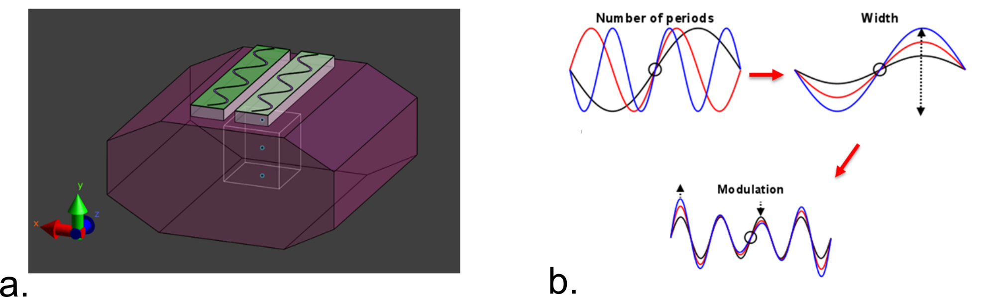
Finite difference time-domain simulations (Sim4Life, Zurich Medtech, Zurich, Switzerland) were used to model two sinusoidal shaped dipole antennas on a phantom with tissue-like properties (σ = 0.37 S/m εr= 34). The geometry of the dipole antennas was varied by changing the number of periods, the width and the modulation of the sinusoidal geometry (figure 1). The length of the dipole antennas was kept equal to the length of the fractionated dipole antenna for 10.5T in all cases1,6. Phase shimming was applied on a cubic region of interest (ROI, 10 cm3) located at a depth of 10 cm in the phantom. The different antenna geometries were evaluated by calculating the 10g-averaged peak SAR, and by assessing B1+ in the ROI. The optimum antenna was selected based on the highest B1+/√SAR10g in the ROI. The new antenna design was compared to a previous design by simulating two 12-channel setups on the torso of Duke11: a setup consisting of fractionated dipole antennas and a setup consisting of the optimized antenna (snake antenna). For validation of the simulations, B1+-maps (actual flip angle method, TR 20/120 ms12) and Magnetic Resonance Thermometry maps (MRT, Proton-Resonance Frequency-shift method13) were acquired experimentally on the Siemens Magnetom 10.5T system, and compared to numerical simulations. MRT was done on a Hydroxyethyl Cellulose (HEC) phantom, containing 2.97 g NaCl/L and 14 g HEC/L. RF heating for the MRT experiments was performed using a protocol with the following relevant scan parameters: input voltage 120 V, TR 7.5 ms, pulse length 0.5 ms, sinc bandwidth product = 1, total heating time 4:00 minutes, flip angle 180o, duty cycle 6.67%.Results
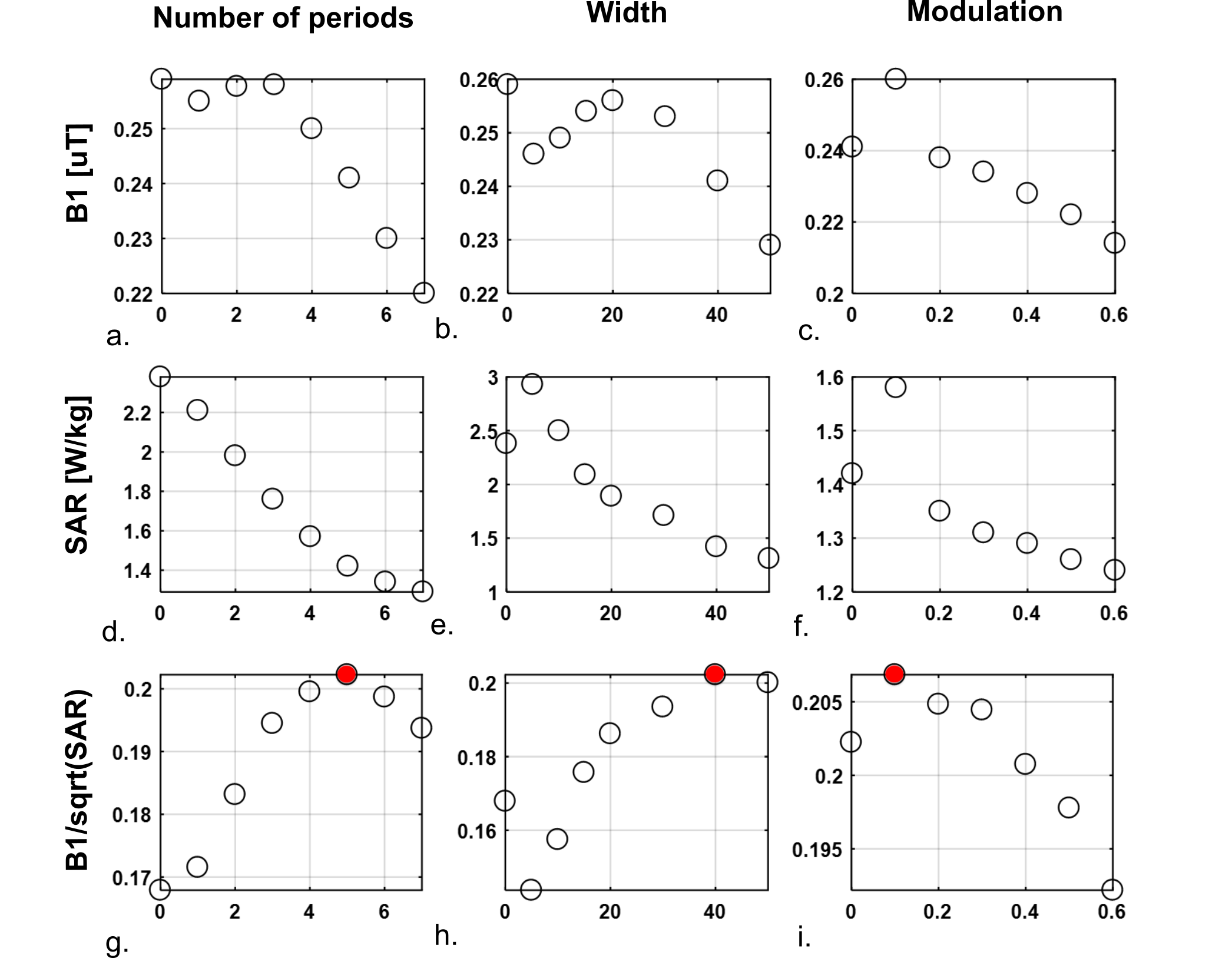
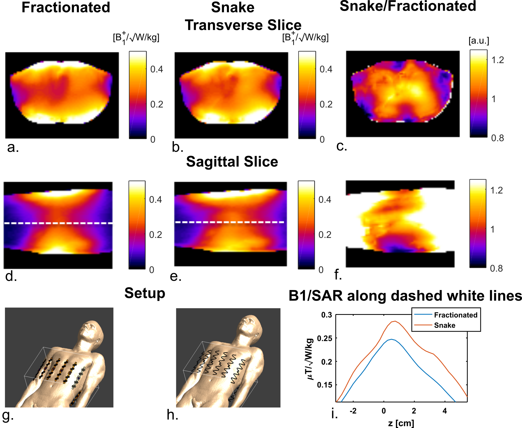
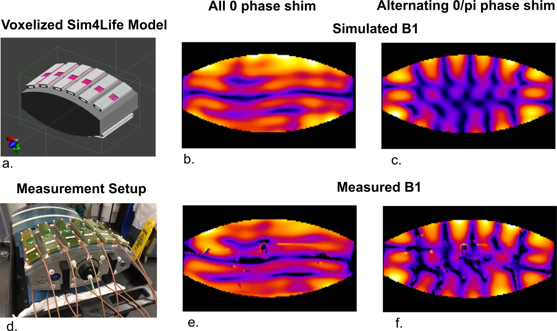
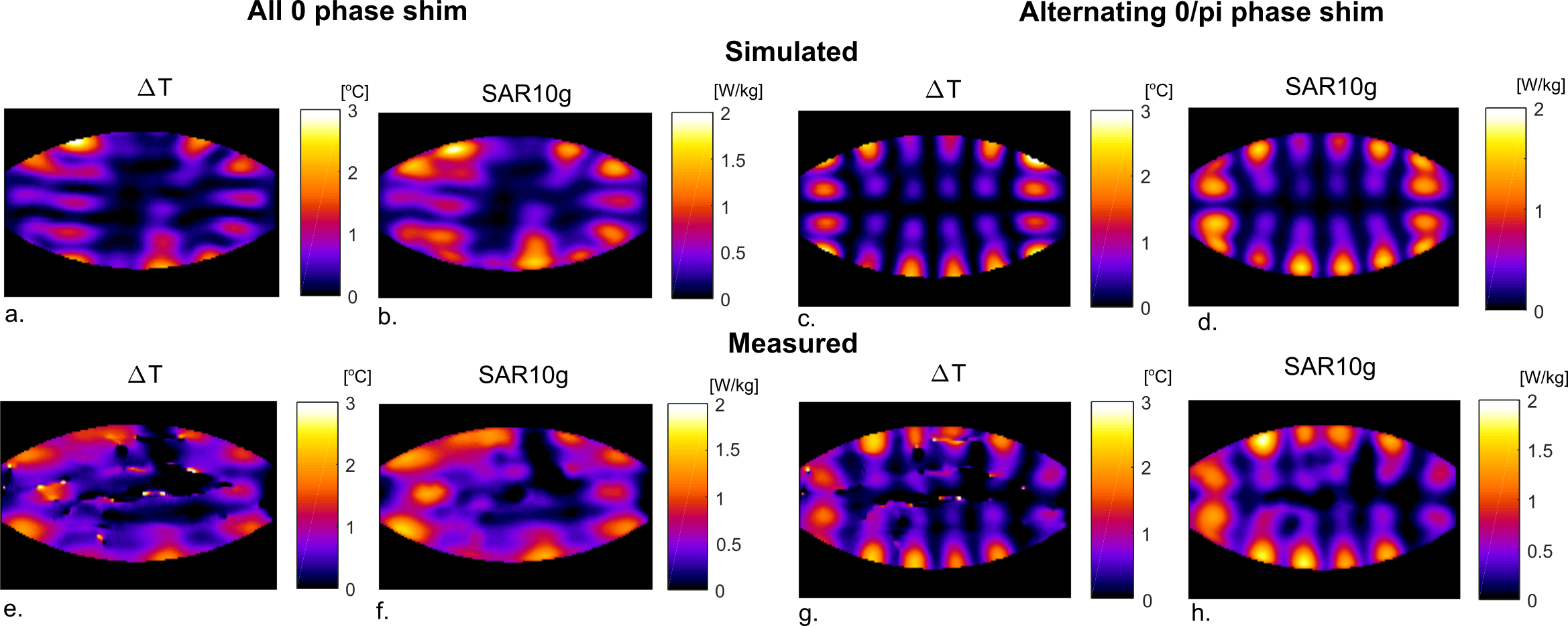
Figure 2 shows the effect of antenna geometry on antenna performance. Increasing the number of periods, the width or the modulation decreases SAR but also decreases B1+. However, transmit efficiency does not decrease at the same rate as SAR, resulting in certain optimal parameters to exist. Based on these simulation results, an antenna geometry with 5 periods, a meander width of 40 mm and a modulation of 0.1 was chosen as the optimum geometry. This antenna design is referred to as the snake antenna. Figure 3 shows field distributions in a transverse slice through the torso for a setup of 12 fractionated dipoles and snake antennas. The field distributions shown here represent the optimum B1+ in every voxel, normalized to the maximum SAR10g for a phase-only shim solution. In the central region of the slice, B1+/√SAR10g increases up to 25% when using the snake antenna array. Figure 4 shows a comparison of simulated and measured B1+-maps in a phantom for two different phase settings (all phases 0, or alternating 0/pi phase offset per channel). Simulation results were normalized per channel based on the ratio between simulated and measured single-channel B1+-maps. Figure 5 shows simulated and measured temperature and SAR maps that were obtained using the same power normalization and phase offsets.The field patterns and the scale of the simulations are in good correspondence for both the B1+-maps as the MRT results.Discussion
It was demonstrated in simulations that by optimizing the dipole geometry, the B1+/√SAR10g level can be increased up to 25%. This implies that for an equal B1+, SAR levels are 36% lower, making it potentially possible to decrease the scan time by the same amount. Simulations results were validated by means of B1+-maps and MR Thermometry and are in good correspondence. The comparison of simulation and experimental results will be submitted to the US Food and Drug Administration for approval of scans on human volunteers.Conclusion
By adapting the geometry of a dipole antenna it was possible to decrease effective peak local SAR levels by 36%. Simulation results were validated experimentally by B1+-maps and MR Thermometry.Acknowledgements
S10 Grant RR029672 “Console for 10.5 Tesla Whole Body MRI System”
BTRC Grant P41 EB015894
Dutch Technology Foundation STW Grant 13783
References
1. Raaijmakers AJE, Ipek O, Klomp DWJ, Possanzini C, Harvey PR, Lagendijk JJW, den Berg CAT. Design of a radiative surface coil array element at 7 T: The single-side adapted dipole antenna. Magn Reson Med. 2011; 66:1488–1497.
2. Wiggins GC, Zhang B, Lattanzi R, Chen G, Sodickson DK. The Electric Dipole Array: An Attempt to Match the Ideal Current Pattern for Central SNR at 7 Tesla. Proc. Intl. Soc. Mag. Reson. Melbourne. 2011; 541.
3. Winter L, Özerdem C, Hoffmann W, Santoro D, Müller A, Waiczies H, Seemann R, Graessl A, Wust P, Niendorf T. Design and Evaluation of a Hybrid Radiofrequency Applicator for Magnetic Resonance Imaging and RF Induced Hyperthermia: Electromagnetic Field Simulations up to 14.0 Tesla and Proof-of-Concept at 7.0 Tesla. PLoS One. 2013; doi: 10.1371/journal.pone.0061661.
4. Raaijmakers AJE, Italiaander M, Voogt IJ, Luijten PR, Hoogduin JM, Klomp DWJ, van den Berg CAT. The fractionated dipole antenna: A new antenna for body imaging at 7 Tesla. Magn Reson Med. 2016; 75:1366–1374.
5. Oezerdem C, Winter L, Graessl A, Paul K, Els A, Weinberger O, Rieger J, Kuehne A, Dieringer M, Hezel F, Voit D, Frahm J, Niendorf T. 16-channel bow tie antenna transceiver array for cardiac MR at 7.0 tesla. Magn Reson Med. 2016; 75:2553–2565.
6. Ertürk MA, Wu X, Eryaman Y, Van de Moortele P-F, Auerbach EJ, Lagore RL, DelaBarre L, Vaughan JT, Uğurbil K, Adriany G, Metzger GJ. Toward imaging the body at 10.5 tesla. Magn Reson Med. 2016; 77:434–443.
7. Ertürk MA, Raaijmakers AJE, Adriany G, Ugurbil K, Metzger GJ. A 16-channel combined loop-dipole transceiver array for 7 Tesla body MRI. Magn Reson Med. 2016; 77:884–894.
8. Wiggins GC, Lakshmanan K, Chen G (2015) The Distributed Inductance Electric Dipole Antenna. Proc. Intl. Soc. Mag. Reson. Vancouver. 2015; 23:3100.
9. Steensma BR, Obando AV, Klomp DWJ, van den Berg CAT, Raaijmakers AJE. Body imaging at 7 tesla with much lower SAR levels: an introduction of the Snake Antenna Array. Proc. Intl. Soc. Mag. Reson. Singapore. 2016; 0395
10. Connell IRO, Menon RS. Shape-Optimization of Electric Dipoles for Human Head Imaging at 7 Tesla. Proc. Intl. Soc. Mag. Reson. Med. 2017; 1130.
11. Kuster AC and WK and EGH and KH and MZ and EN and WR and RJ and WB and JC and BK and PS and H-PH and J. The Virtual Family—development of surface-based anatomical models of two adults and two children for dosimetric simulations. Phys Med Biol. 2011; 55:N23.
12. Yarnykh VL. Actual flip-angle imaging in the pulsed steady state: A method for rapid three-dimensional mapping of the transmitted radiofrequency field. Magn Reson Med. 2007; 57:192–200.
13. Rieke V, Butts, K. MR Thermometry. J magn Reson Imaging. 2008; 27(2): 376-390.
Figures