0137
The MRF Array: an iPRES Coil Array for Accelerated Magnetic Resonance Fingerprinting1Department of Radiology, Case Western Reserve University, Cleveland, OH, United States, 2Quality Electrodynamics, Mayfield Heights, OH, United States, 3Department of Biomedical Engineering, Case Western Reserve University, Cleveland, OH, United States
Synopsis
Magnetic Resonance Fingerprinting (MRF) depends on spatially and temporally incoherent encoding fields for fast quantitative imaging. However the achievable encoding is limited by hardware. The iPRES concept, which adds ΔB0 and B1+ encoding to a receive array, is an excellent candidate for additional encoding for MRF. Here we present preliminary results of a 16 channel iPRES array, referred to as the MRF array. The MRF array uses in-bore power amplifiers to provide vastly increased encoding capabilities while minimizing the cost of additional hardware. Such encoding schemes are expected to allow for acceleration of quantitative imaging techniques such as MRF.
Introduction:
MRF1 benefits from spatially and temporally incoherent encoding, but normal MRI scanner hardware limits us to spatially homogeneous excitations and linear gradient encoding. It has previously been proposed2,3 that the iPRES4 coil concept be used to allow spatio-temporal manipulation of B1+ and ΔB0. Here we present an array of 16 iPRES coils, referred to as the MRF array, for use at 3T. The MRF array integrates the RF receive and transmit amplifiers for efficient B1- and B1+ encoding, as well as DC current drivers for ΔB0 encoding, inside the MRI bore. By allowing all three fields to be conveyed spatially and temporally, The MRF array promises transformative encoding capability for MRF experiments while minimizing the cost and complexity of the added hardware.Methods:
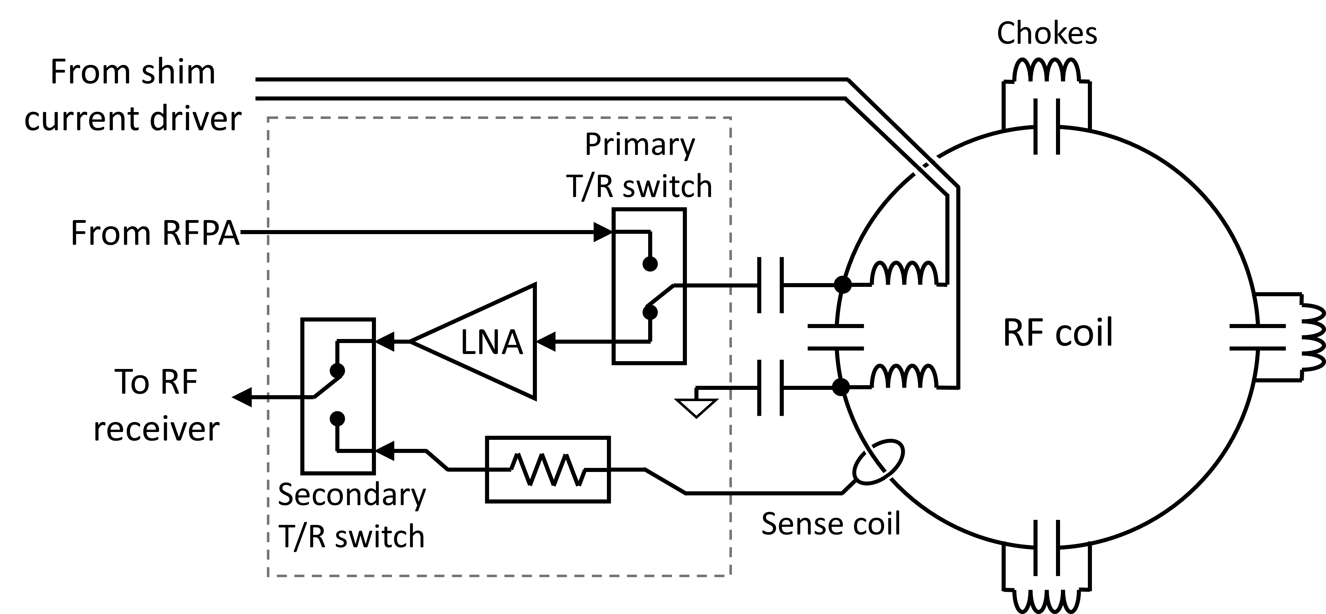
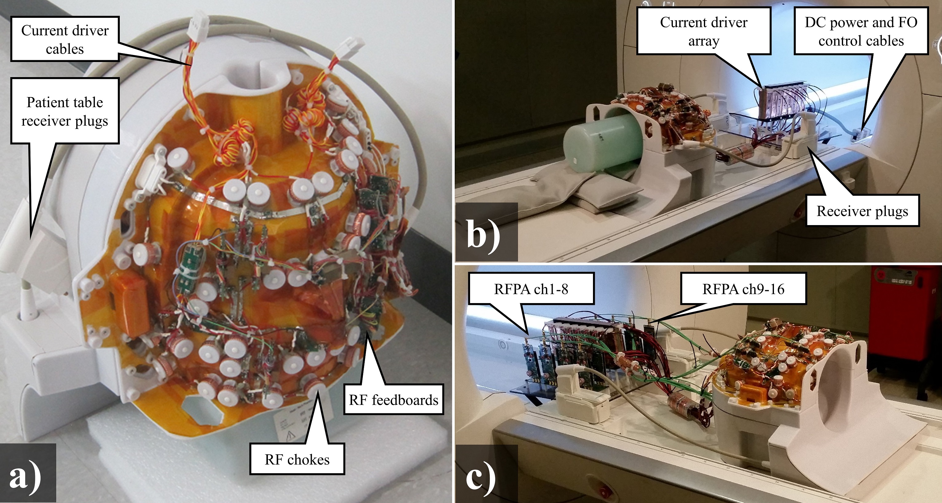
16 channel MRF array: Previously we had presented a prototype iPRES element2 with a RF feed board as described in figure 1. The RF feed board interfaces the RF transmit and receive amplifiers to the coil, and permits measurement of the coil current during transmit pulses. Figure 2a) shows a photograph of the MRF array, which expands this architecture to a 16 channel head array for 3T. The array is meant to be used with a 16 channel array of DC current drivers5 and a 16 channel high efficiency RFPA array6,7 located inside or next to the scanner bore. Figure 2b) shows the MRF array connected to the current drivers during an imaging experiment. The RFPAs have yet to be used in imaging experiments for lack of an appropriate pTX control interface. All imaging experiments were performed with the TX ports unconnected, while the scanner’s body coil was used for excitation. Figure 2c) shows what the intended full assembly, including the RFPAs.
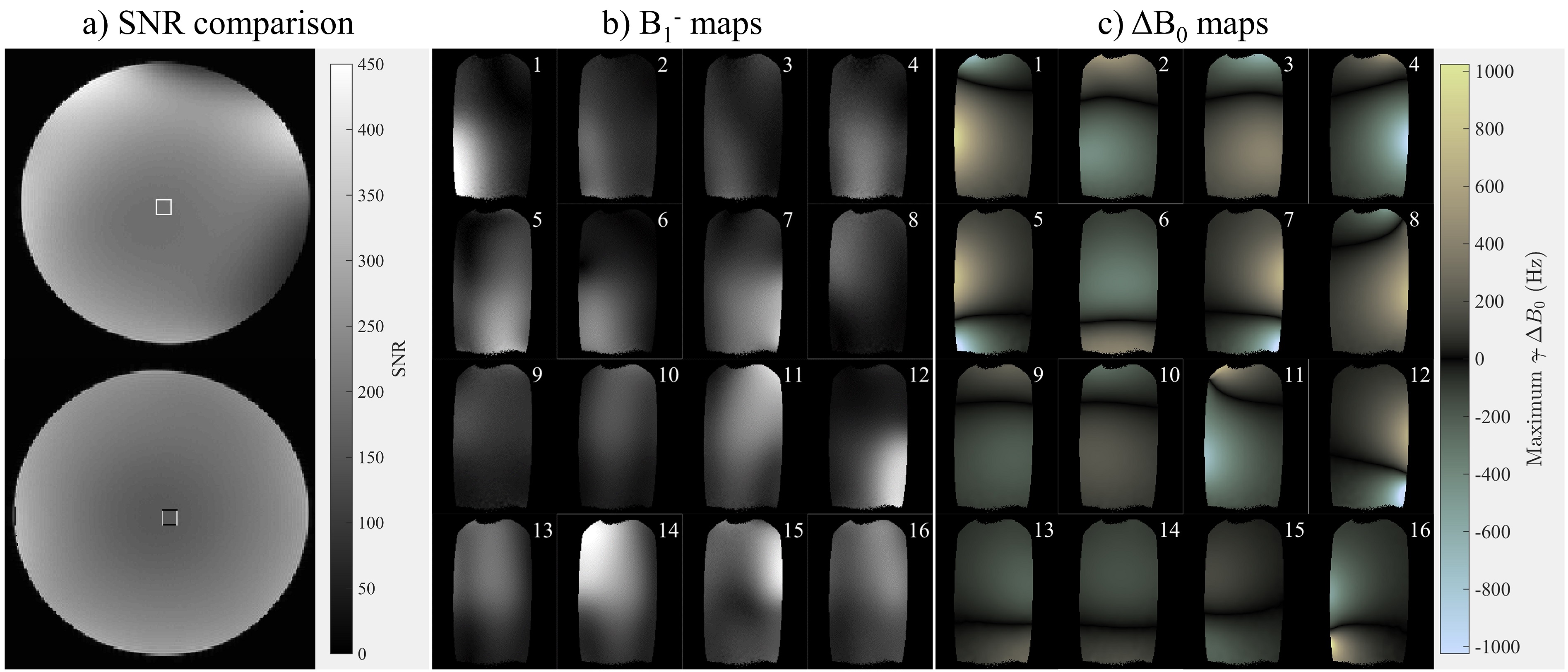
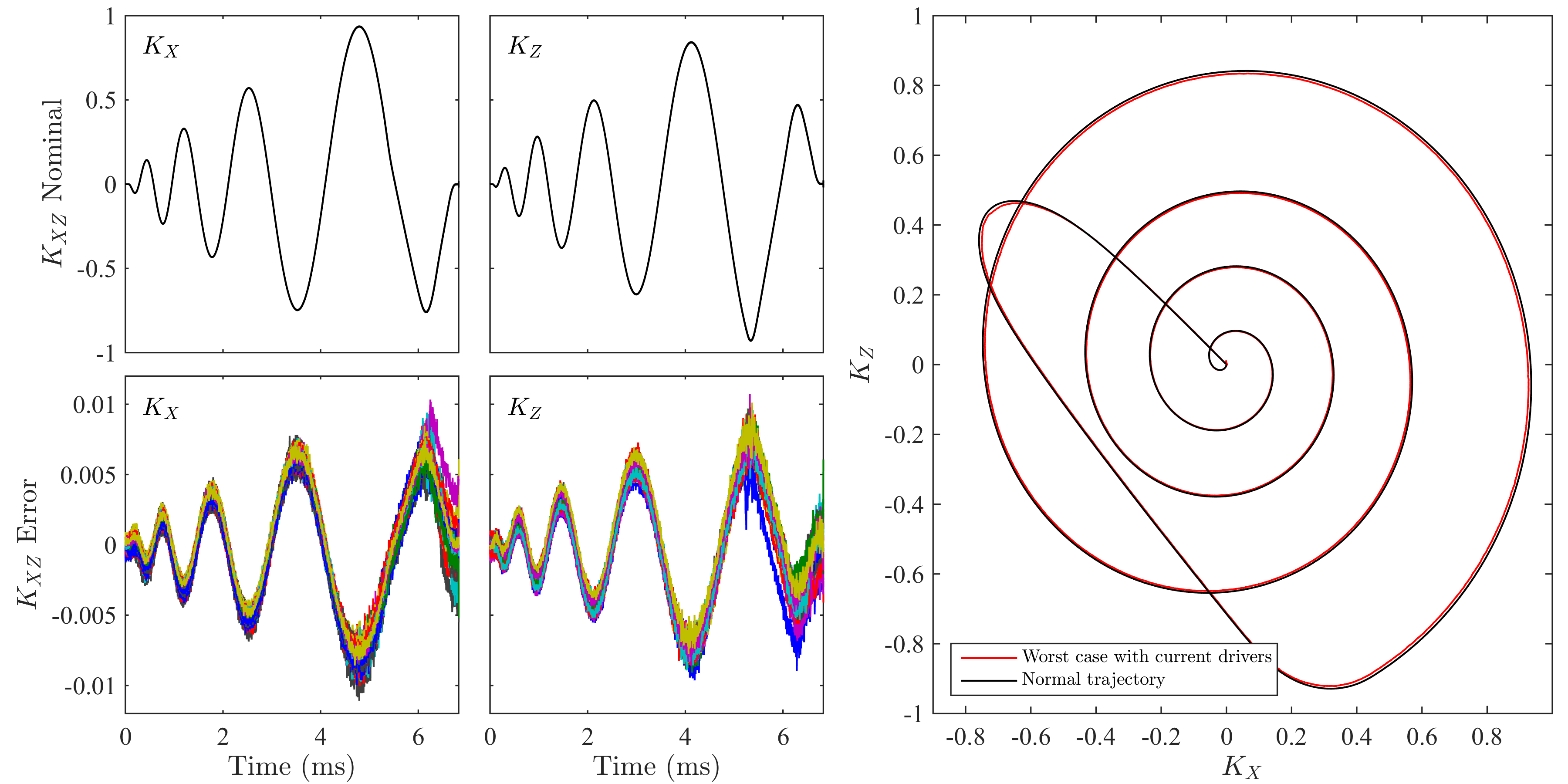
Imaging experiments: The MRF array was evaluated with imaging experiments on a Siemens Skyra 3T scanner using a 5.3L saline phantom. The SNR of the MRF array was compared to a 20 channel Siemens head/neck array (without the current drivers connected). The array’s ΔB0 and B1- sensitivities were also mapped. Spiral trajectories were also measured8 to investigate whether gradient-induced emf in the iPRES coils’ DC paths could affect image encoding. Measurements were also performed to determine the impact of the current drivers on SNR.
Results:
Coil sensitivity: Figure 3a) demonstrates that the receive sensitivity of the array is comparable to vendor head arrays when the current drivers are disconnected. Figures 3b) and 3c) show the B1- and ΔB0 sensitivity maps in a coronal slice. It can be seen that the ΔB0 and B1- maps of each element are unique, suggesting that each coil adds multiple degrees of freedom to signal encoding. Figure 4 shows a summary of the trajectory measurement results for a coronal spiral trajectory. The peak shift observed in k when using the current drivers was just 1.2% of kmax.
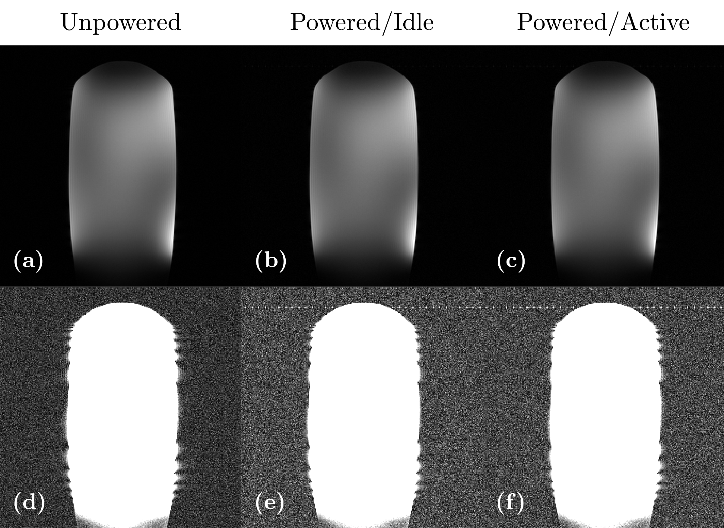
Radiofrequency interference: When the current drivers were connected and powered, we found that background RMS noise rose by 30%. The added noise was predominantly white, as opposed to zipper artifacts which typically originate from switching circuits like the current drivers. Currently it is believed that this added noise originates from a microcontroller on the current drivers’ backplane, which was unshielded. Some coherent interference manifested as a zipper artifact. This artifact could be moved out of the FOV by simply adjusting the reference clock to the driver backplane. Activating the current drivers’ switchmode power stages did not cause an observable increase in the background noise or zipper artifact.
Discussion and conclusions:
Preliminary work2,3 has suggested that additional spatio-temporal encoding can improve robustness against aliasing artifacts and increase the uniqueness of signal evolutions from different tissues. Ultimately we expect that optimized use of novel encoding schemes will allow for significant acceleration in MRF.
Currently we have implemented ΔB0 encoding using an array of high efficiency current drivers, adding 16 degrees of freedom to the sequence encoding. We anticipate that proper shielding of the current drivers’ microcontroller will reduce radiofrequency interference in the receive chain below the noise floor. In the near future, we aim to add another 32 degrees of freedom to the array with pTX using 16 efficiency RFPAs6. By combining the array with low cost, high efficiency amplifiers near the MRI bore, we aim to demonstrate that vast encoding capability can be achieved while minimizing hardware overhead.
Acknowledgements
This work was supported by Siemens healthcare and NIH grants 1R01EB016728 and 1R01BB017219.References
1. Ma, D. et al. Magnetic resonance fingerprinting. Nature 495, 187–192 (2013).
2. Twieg, M. et al. Compact iPRES coil assembly for Magnetic Resonance Fingerprinting. 25th ISMRM (2017).
3. Mehta, B. et al. Improving Uniqueness of MRF Signal Evolutions Using an Integrated Parallel Receive, Excitation & Shimming (iPRES) Coil Array. in (2017).
4. Han, H., Song, A. W. & Truong, T.-K. Integrated parallel reception, excitation, and shimming (iPRES). MRM 70, 241–247 (2013).
5. Twieg, M. & Griswold, M. A. In-Bore High Efficiency Current Driver. 25th ISMRM (2017).
6. Twieg, M. & Griswold, M. A. High efficiency radiofrequency power amplifier module for parallel transmit arrays at 3 Tesla. MRM (2016).
7. Twieg, M. et al. A 16 Channel Head-Only PTX Array Using High Efficiency In-Bore RFPAs at 3T. 25th ISMRM (2017).
8. Duyn, J. H., Yang, Y., Frank, J. A. & van der Veen, J. W. Simple Correction Method for k-Space Trajectory Deviations in MRI. JMR 132, 150–153 (1998).
Figures