0070
Prospective motion correction with NMR markers using only native sequence elements1Institute for Biomedical Engineering, ETH Zurich and University of Zurich, Zurich, Switzerland
Synopsis
A new method for tracking active NMR markers is presented. It requires no alterations of the MR sequence and can be used for prospective motion correction (PMC) in brain MRI. The proposed method collects high-frequency information present due to gradient switching from multiple short, temporally separated snippets within one or more TR of the given sequence. A tracking precision on the order of 10µm and 0.01° (RMS) for translational and rotational degrees of freedom is obtained. The method is demonstrated in-vivo with high-resolution 2D T2*-weighted GRE and 3D MPRAGE brain scans.
Introduction
Head motion is a confounding factor in brain MRI. Retrospective correction methods mitigate motion artefacts at the level of image reconstruction1,2. Alternatively, prospective motion correction (PMC) performs real-time updates of scan geometry based on head tracking3. Optical tracking methods offer high sensitivity and operate independently of MRI4-6. However, they require a line-of-sight between head-mounted markers and a camera, a demand that can be hard to meet with dense receiver arrays. MR navigators, on the other hand, require additional sequence elements to estimate head motion7,8 and thus generally come at the expense of scan time. Another set of methods derive the positions of head-mounted NMR markers from FIDs acquired in the presence of suitable gradient dynamics9,10. This approach has been shown to match the tracking precision of optical techniques without the line-of-sight requirement. However, it has also been hampered by the need for sequence elements dedicated to the tracking purpose. The present work aims to overcome this limitation by NMR marker tracking without sequence alteration. This is achieved by distributed harvesting and joint algebraic processing of signal snippets from short-lived markers11. The proposed approach is demonstrated by assessing tracking precision and by PMC in high-resolution brain scans.Methods
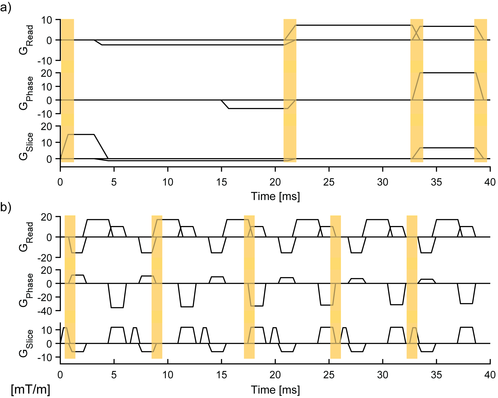
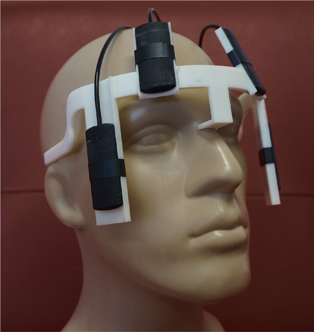
Short-lived NMR markers are used to acquire signal snippets in rapid succession, covering gradient switching events that are natively present in each given imaging sequence (Fig.1). This enables fast marker localization and provides high-frequency signal content for robust position fitting10. For good conditioning, snippets are chosen such as to capture linearly independent dynamics on the three gradient axes. Phase accrual of an NMR marker at position $$$\textbf{r}$$$ is described by a linear model: $$\phi(\textbf{r},t) = \gamma \int_0^t (\textbf{g}(\tau)\cdot r + g_0 (\tau))d\tau + w_0(\textbf{r})t+\eta(t),$$ with $$$\textbf{g}(\tau)$$$ and $$g_0(\tau)$$ denoting the linear and uniform field components, the static component $$$\omega_0(\textbf{r})$$$, the gyromagnetic ratio $$$\gamma$$$, and noise $$$\eta(t)$$$. Arranging time-discrete data in vectors, signal phase is translated into frequency by a difference operator $$$\textbf{D}$$$, followed by a projection operator $$$\textbf{F}$$$ that discards DC and low frequencies. The least-squares solution for the marker position then reads $$$\textbf{r}=(\textbf{FG})^+\textbf{F}(\gamma^{-1}\textbf{D}{\phi} -\textbf{g}_0)$$$. $$$\textbf{G}$$$ and $$$\bf{g_0}$$$ reflect 1st– and 0th-order field dynamics and are determined by calibration measurement. Scans were performed on a 7T Philips Achieva system (Philips Healthcare, Best, NL) with a 32-channel receive array (Nova Medical, Wilmington, MA). Four 19F NMR field probes12 (diameter=1.3mm, T1=2.1ms) were used with a custom-built acquisition system13. Tracking precision was assessed by computing the standard deviation of rigid-body parameters in a static setting and imaging a phantom (Agar/NiCl2) with and without PMC. For in-vivo PMC, markers were attached to the head of a healthy volunteer using the setup shown in Fig.2. A T2*-weighted GRE scan (0.3x0.3x2mm³, FOV: 230x230x58 mm³, TE/TR=25/48ms, flip-angle=45°, 15 slices, duration: 9:13min) was performed and the volunteer was asked to hold still. Moreover, a 3D-MPRAGE sequence (0.7x0.7x1.4 mm³, FOV: 220x220x80 mm³, TE/TR=2.9/6.5ms, flip-angle=7°, TI=1200ms, 2 averages, duration=9:42min) was performed with instructed subject motion. All scans were performed with and without PMC. Snippets were placed as indicated in Fig.1a/b.Results
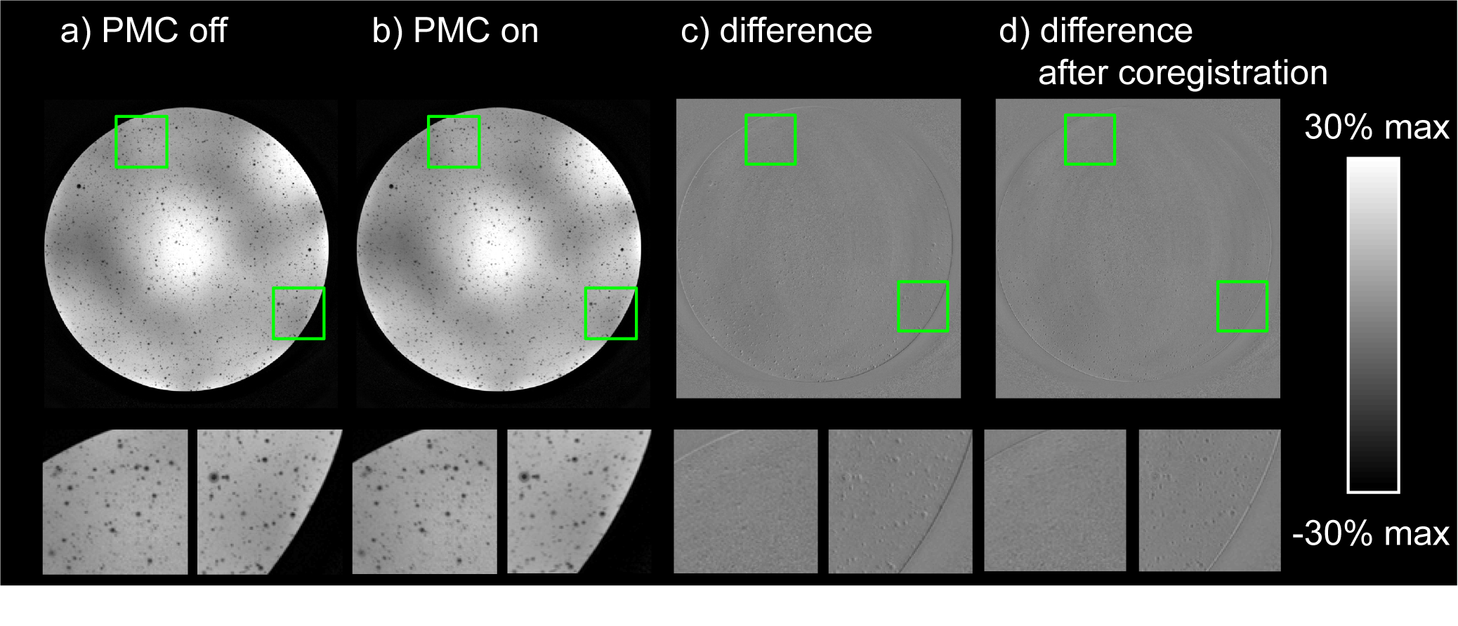
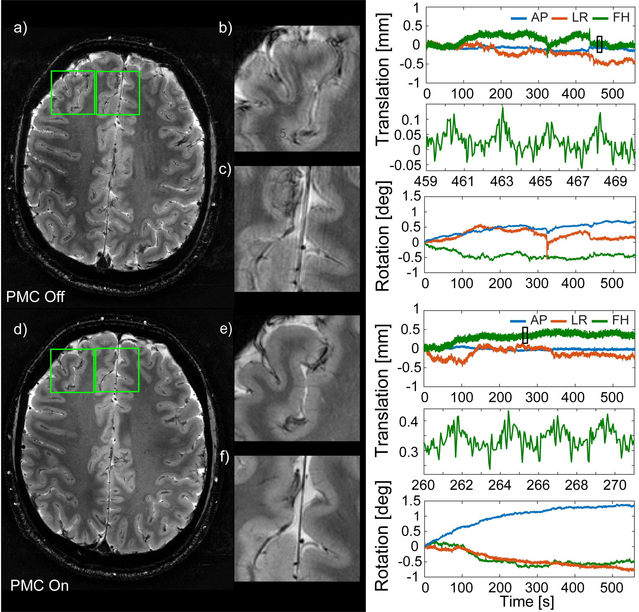
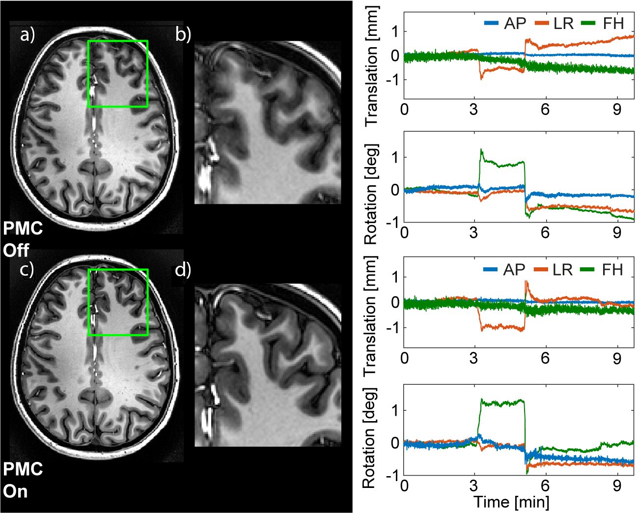
The precision of translation and rotation tracking was approximately 10µm and 0.005°, respectively, for the T2* sequence, and 10-30µm and 0.01° for the MPRAGE sequence. PMC did not introduce any conspicuous artefacts in the phantom image (Fig.3a/b). Only image subtraction (Fig.3c/d) reveals very subtle differences caused by finite tracking precision, amounting to few percent of the voxel dimensions. Figure 4 shows images obtained with the T2* sequence without intentional subject motion along with corresponding motion data. Significant motion artefacts resulted even from subtle involuntary head motion (Fig. 4a-c). PMC yielded a substantially clearer image of finer detail (Fig.4d-f). Head motion was confined to roughly +/-1mm and +/-1° (Fig. 4). In the MPRAGE case, an instructed small head rotation visibly degraded image quality in the uncorrected image (Fig.5a/b), while PMC again greatly improved the delineation between white and grey matter (Fig.5c/d). The motion pattern was similar in both scans (Fig. 5).Discussion
The proposed method permits high-precision tracking of NMR markers without the need to alter given MRI sequences. It thus newly reconciles high tracking performance and sequence versatility with immunity to line-of-sight issues. One caveat is that sequences may exhibit brief time periods without phase encoding or phase spoiling, e.g. at . In these cases, the corresponding coordinate will remain without update for typically a few seconds. When critical, this pause can be avoided by an offset of the spoiler gradient in the same direction, a straightforward option unless the sequence is intended to be fully balanced. The need for calibration measurement of gradient dynamics can be overcome by real-time field tracking in the laboratory frame14.Acknowledgements
No acknowledgement found.References
[1] Atkinson et al, IEEE Trans Med Imaging 16:903-910 (1997)
[2] Loktyushin et al, MRM 73:1457-1468 (2015)
[3] Maclaren et al, MRM 69:621-636 (2013)
[4] Zaitsev et al, Neuroimage 31:1038–1050 (2006)
[5] Maclaren et al, PLoS One 7:e48088 (2012)
[6] Stucht et al, PLoS One 10:e0133921 (2015)
[7] Tisdall et al, MRM 68:389-399 (2012)
[8] van der Kouwe et al, MRM 56:1019-1032 (2006)
[9] Ooi et al, MRM 62:943-954 (2009)
[10] Haeberlin et al, MRM 74:647-660 (2015)
[11] Aranovitch et al, MRM 79:2046-2056 (2018)
[12] De Zanche et al, MRM 60: 176–186 (2008)
[13] Dietrich et al, MRM 75:1831-1840 (2016)
[14] Aranovitch et al, Proc. Intl. Soc. Mag. Reson. Med. 25 #0300 (2017)
Figures