0029
3D imaging with a portable MRI scanner using an optimized rotating magnet and 1D gradient coil1Massachusetts Institute of Technology, Cambridge, MA, United States, 2Athinoula A Martinos Center for Biomedical Imaging, Charlestown, MA, United States, 3Harvard Medical School, Boston, MA, United States
Synopsis
A low-cost portable brain MRI scanner could extend the reach of brain MRI to remote locations and point-of-care situations and extend the use of MRI into monitoring applications. We previously presented 3D imaging in a portable magnet without gradient coils using the natural field variation of a rotating permanent magnet for in-plane encoding and RF phase gradients for encoding the third direction. In this work, we show that an efficient gradient coil can phase-encode the third direction in a single shot CPMG train with minimal current (~2A) allowing low-cost amplifiers and negligible power needs, acoustic noise or heating.
Introduction
Halbach arrays of permanent magnets can form lightweight, cryogen and power-free magnets potentially useful for brain imaging at low field (~0.1 T) in situations where it is difficult to site conventional systems or where point-of-care monitoring is needed. We demonstrated 2D generalized projection imaging using rotation of a lightweight Halbach magnet intended for brain imaging3 and later optimized the field pattern for favorable rotational encoding.2 We also explored encoding along the length of the cylinder using RF phase gradients (TRASE)4 in order to avoid the power, cooling and acoustic noise issues of conventional gradient encoding. In this work, we address encoding in the third direction via use of a compact, unshielded gradient coil. While the use of a conventional gradient for image readout is difficult in an inhomogeneous magnet, phase encoding during a spin echo train side-steps the problems from magnet inhomogenieties since they are refocused.5 The unshielded gradient is efficient enough that only a few amps of current are needed, reducing amplifier expenses, eliminating water cooling, and rendering the encoding nearly silent. We show that the system is sufficient to perform the 1D encoding in a single shot of a CPMG echo train, producing 3D encoding in the lightweight, portable system.Methods
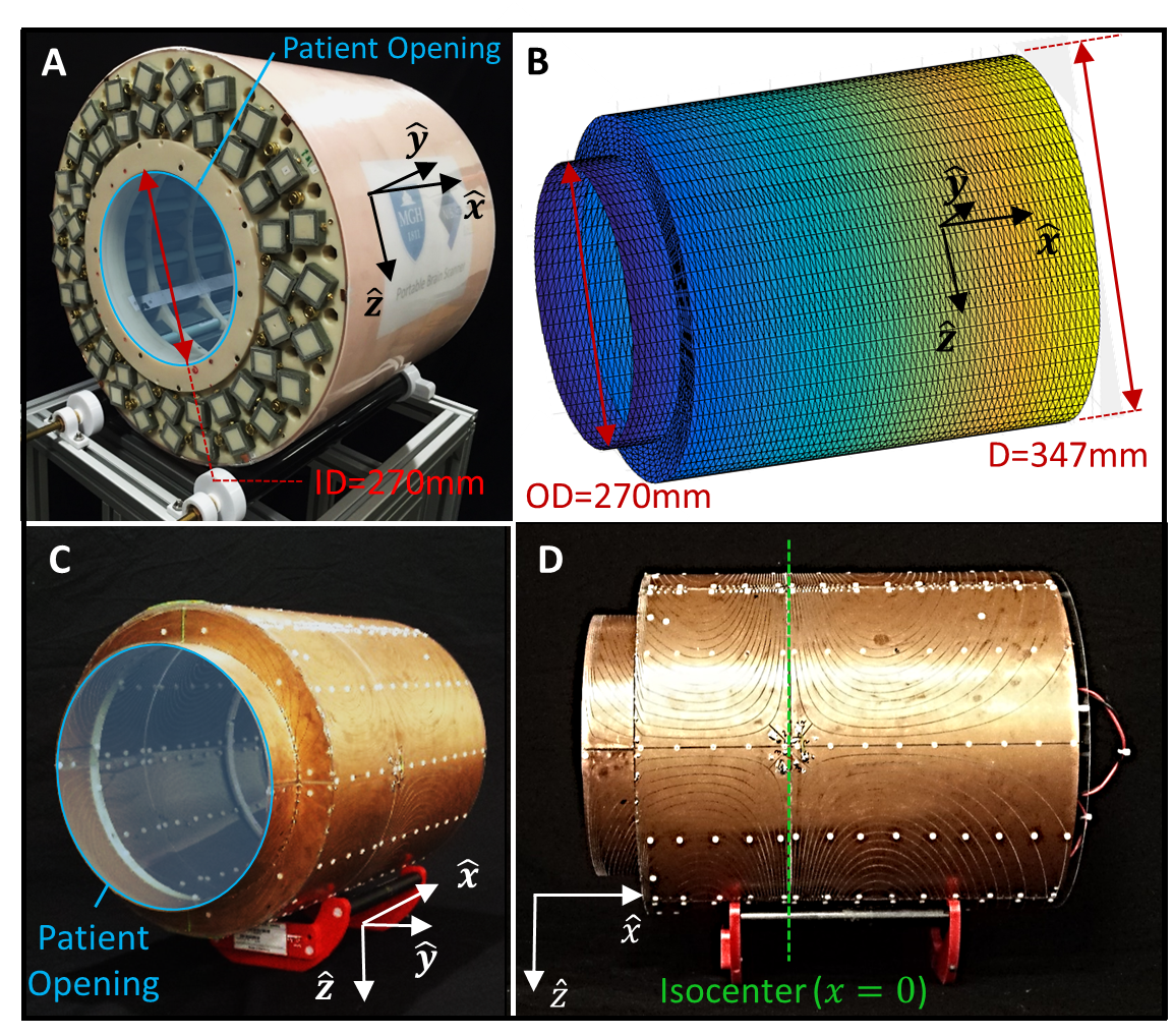
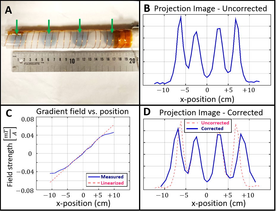
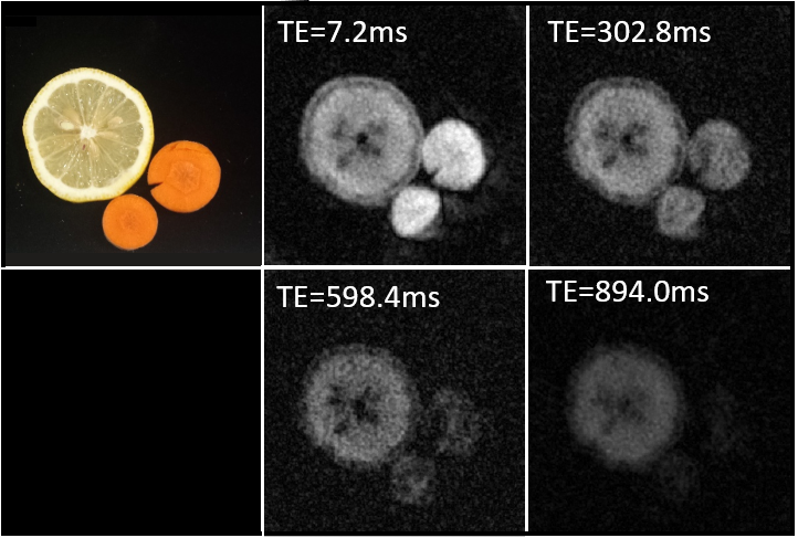
A single-axis, unshielded gradient was designed and tested for encoding the x-direction (along cylinder) of the Halbach magnet. The gradient coil fits on a tiered, bi-cylindrical surface (Figure 2B) to maximize both the length and interior bore. The winding pattern optimized gradient linearity in a 20cm DSV using current paths designed with a BEM stream function optimization using freely-available software1. We then routed the current paths onto a PCB. The coil was numerically assessed using a Biot-Savart simulator and compared to the field measured with a robotic Hall-sensor. Gradient performance was also assessed using a 17.5cm length linear “7-ball phantom” oriented along the phase encode direction (Fig. 3A): of four 2.54cm H2O spheres and an empty sphere between each fluid-filled pair. A CPMG acquisition with 41 echoes (each a phase encode step) was used. Gradient blips were of in duration with a maximum current of 0.75A. 3D images of fruits and vegetables (Figures 4+5) were acquired using the gradient coil for blipped phase encoding along the x-axis during a spin echo train. The generalized projections generated by magnet rotations encoded the y-z plane3. The long echo train allowed multiple 3D images, each with a different TE. Images were reconstructed by performing the inverse DFT along the phase encode/x-axis, and subsequently performing an iterative encoding matrix reconstruction in the y-z plane.Results
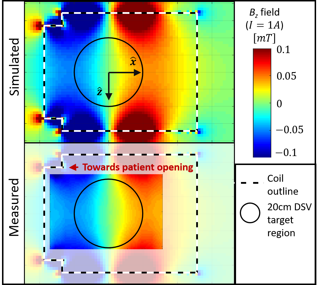
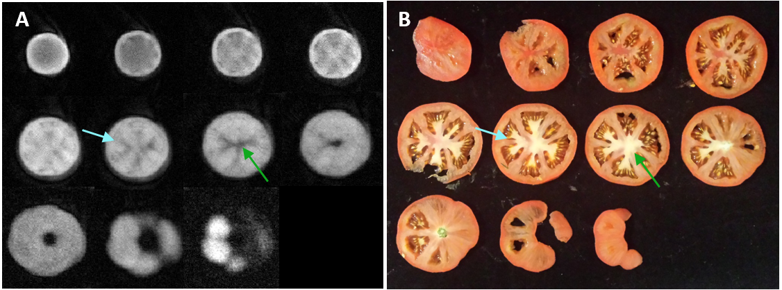
The constructed gradient coil is shown in Figure 1C+D. The coil was measured to have a DC resistance of , efficiency at isocenter of 0.602 mT/m/A, max slew rate o 56.3 mT/m/msf (with +/-60V drive), and linearity deviation of 26% over the 20cmDSV. Figure 2 shows simulated and measured field maps in the x-z plane. A projection image of the 7-ball phantom is shown in Figure 3B, showing all four water-filled spheres, spanning 17.5cm. Because of non-linearities in the gradient field (Figure 3C), the peaks are not of uniform size and spacing. In the corrected projection, the spacings between adjacent peaks were: 4.4cm, 5.3cm, 5.1cm compared with the nominal 5.1cm Figure 4A shows 11 of 21 partitions (thickness=2.9mm) from a 3D image of an intact tomato. Data were averaged across TEs. We then sliced the tomato for comparison (Figure 4B). Figure 5 shows a single partition from the 3D images of a lemon and two carrots reconstructed at the 4 different TEs, showing the longer T2 of the lemon.Discussion
We have demonstrated phase encoding across 17.5cm using a low-current (<2.5A) gradient coil compatible with our rotating, portable MRI system. The combination of 1D phase-encoding and rotational projection imaging yielded full 3D imaging. Going forward, we will extend this work allow imaging across a head-sized FOV in all dimension, enabling whole-brain 3D imaging.Acknowledgements
The authors thank Thomas Witzel, Robin Armstrong, Christopher Vaughn, and Bastien Guerin. Support by NIH R01EB018976, NIH T90DA022759/R90DA023427.References
1. Bringout G, Gräfe K, Buzug TM. Performance of Shielded Electromagnet-Evaluation Under Low-Frequency Excitation. 2015;51:2–5.
2. Cooley CZ, Haskell MW, Cauley SF, Sappo C, Lapierre CD, Ha CG, Stockmann JP, Wald LL. Design of Sparse Halbach Magnet Arrays for Portable MRI Using a Genetic Algorithm. IEEE Trans. Magn. 2017.
3. Cooley CZ, Stockmann JP, Armstrong BD, Sarracanie M, Lev MH, Rosen MS, Wald LL. Two-dimensional imaging in a lightweight portable MRI scanner without gradient coils. Magn. Reson. Med. [Internet] 2015;73:872–83. doi: 10.1002/mrm.25147.
4. Cooley CZ, Stockmann JP, Rosen MS, Wald LL, et al. 3D Imaging in a Portable MRI Scanner using Rotating Spatial Encoding Magnetic Fields and Transmit array spatial encoding (TRASE). In Proc. of the ISMRM, Toronto, Canada, 2015, page 0703.
5. P. J. Prado, B. Blümich, and U. Schmitz, “One-Dimensional Imaging with a Palm-Size Probe,” J. Magn. Reson., vol. 144, no. 2, pp. 200–206, Jun. 2000.
Figures