0028
Antenna Design for Wireless Clock Syncing and Q-spoiling in MRI1Stanford University, Stanford, CA, United States, 2GE Healthcare Inc., Stanford, CA, United States, 3GE Healthcare Inc., Aurora, OH, United States
Synopsis
This work explored the antenna design choices for wireless MRI, specifically for clock synchronization and scanner state detection. Antennas at 1.6GHz for the clock signal, and 3.5GHz for Q-spoil signal were tested for transmit and receive performance. Reflectors were constructed and improvements in antenna path loss were observed. A better understanding of these antennas is necessary to help satisfy link budget requirements.
Introduction
MRI researchers have expressed great interest in development of wireless MRI. Such a system could improve scan workflow and provide easier handling of wieldy coil arrays. However, to achieve this goal requires addressing several challenges. Power, data, and synchronization would now be performed partially or entirely by wireless protocols.
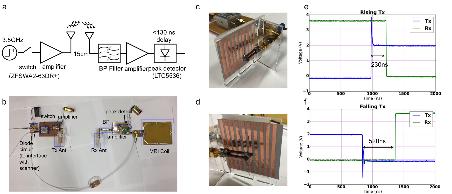
For power, the wireless receive coils could run on battery or be powered wirelessly [1]. Data streaming is feasible with off-the-shelf components that implement 802.11ac/ad WiFi or ultra-wide-band (UWB) technology. The isolated coil must also be prompted with the scanner transmit state, or Q-spoil signal, so that the coil acts accordingly (ie. Q-spoils during Tx; activates LNA and ADCs during Rx) [2]. Finally, the receive coil electronics must obtain a clock signal phase synchronous with the MRI time-base [3] as any phase discrepancy will result in image artifacts.
Central to the transmission of these wireless signals are the antennas. This work focuses on antenna options for transmitting the Q-spoil or clock phase synchronization signals. The antenna choice depends on size, form factor, field pattern and link budget in the MRI bore [4].
Theory
Antenna options include dipoles and full wave loops, which are linearly polarized, or crossed dipoles, which are circularly polarized. Reflectors, such as copper shield or parasitic elements slightly longer than dipoles, direct the gain of the antenna forward, modify impedance, and eliminate uncontrolled reflections from the MRI RF shield.
The antennas must satisfy the link budget requirements. The Q-spoil signal must exceed the RF peak detection threshold. For clock synchronization, the wireless link path loss raises the broadband phase noise floor of the recovered clock. The SNR of this clock signal is inversely related to the rms phase jitter, yielding an integrated time jitter [5] (Fig1) that sets the upper bound performance of the ADC in the receiver electronics.
We have assessed a 3.5GHz (λ=18.7cm) Q-spoil signal and a 1.6GHz (λ=8.6cm) clock signal across 15cm. Consequently the link distance spans the near and far field regions of the antennas. We constructed transmit and receive antennas at 1.6GHz. In addition, we constructed a set of dipoles with parasitic copper reflector strips at 3.5GHz.
Materials and methods
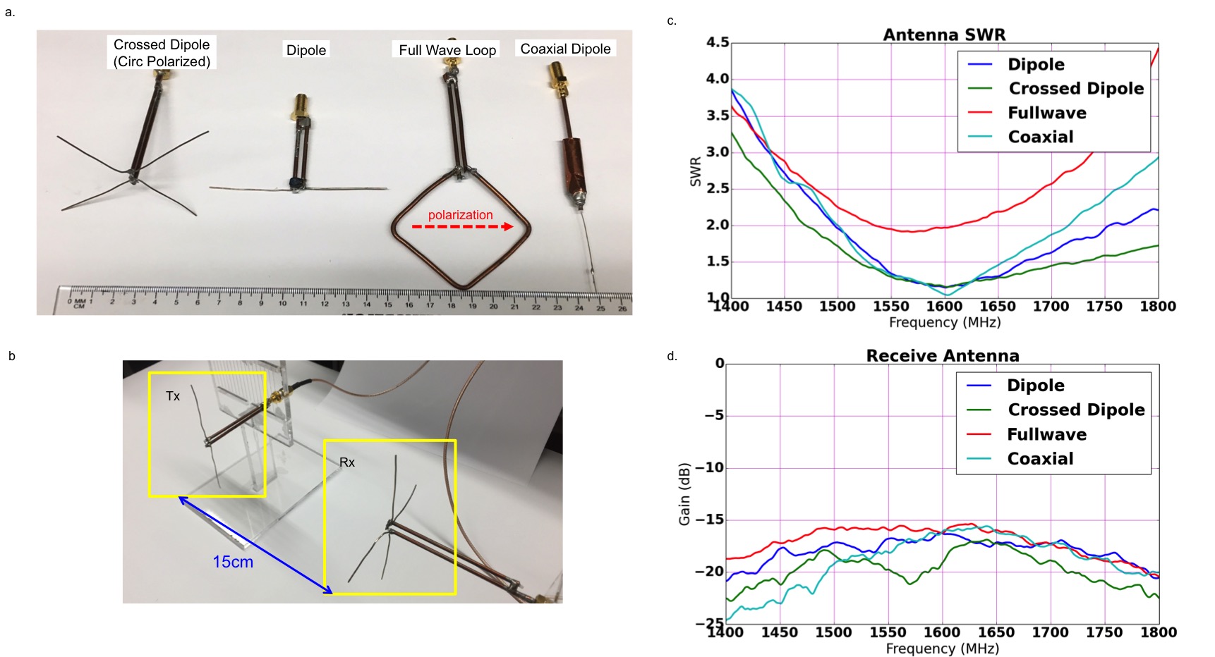
We constructed four receive antennas at 1.6GHz: half wave dipole, crossed dipole, full wave loop, and coaxial dipole (Fig2). The coaxial antenna was constructed with a bazooka balun; the others used a folded balun. We measured antenna SWR to ensure reasonable tuning, and then measured the S21 15 cm path loss of each receive antenna using the same dipole for Tx.
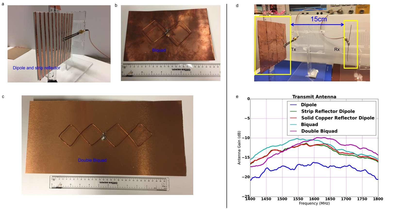
In addition, we constructed five different antennas for transmit: dipole, dipole with solid copper reflector, dipole with copper strip reflectors, biquad, and double biquad. Reflectors were placed ~0.15-0.2λ behind the antennas. S21 measurements were taken with a dipole receive antenna for each transmit antenna 15 cm away. Finally, we constructed compact 3.5GHz dipole antennas and reflectors.
Results
After constructing our 1.6GHz receive antennas, we measured SWR values below 1.3:1 for all except the full wave loop. The full wave loop had an SWR of 2:1. The maximum receive path loss over 15 cm for each receive antenna was better than -16.5dB while the crossed dipole exhibited a loss of -19.1dB.
For transmit antennas at 1.6GHz, the biquad and double biquad had gains of -10.5dB and -10.3dB respectively while the dipole reflector designs had weaker S21 gains by 1.5dB.
With the 3.5GHz antennas, using both transmit and receive strip reflectors, we measured -18.2dB in attenuation, which was an 8.8dB improvement over using the dipoles alone.
Discussion
Adding reflectors on both transmit and receive antennas improved power gain almost 8x. While a solid copper reflector could distort the B1 field, the strip reflectors yielded similar performance and are transparent to B1.
The transmit reflector antennas had similar performance, with the double biquad dual figure 8 pattern being inherently decoupled with B1. A version with copper strip reflectors would be needed however.
Conclusion
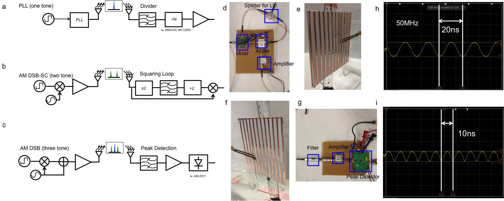
Future work involves using these antennas for clock synchronization by divider, BPSK and AM demodulation (Fig5). For instance, with divider clock recovery [3], the prescalers require an input exceeding -12dBm, which demands at least +1.5dBm transmit power using the biquad and double biquad. This signal could perhaps be even weaker if a reflector is added to the receive antenna. These designs show promise in satisfying our link budget constraints.Acknowledgements
The authors acknowledge the Stanford Graduate Fellowship, National Science Foundation, NIH Grant R01EB008108, R01EB019241, GE Healthcare Research Support.
References
[1] K Byron et al, RF Gated Wireless Power Transfer System, ISMRM 2015, #0707
[2] J Lu, et al Wireless Q-Spoiling of Receive Coils at 1.5T MRI, ISMRM 2017, #1615
[3] J Lu, et al Wireless Clock Transfer for MRI Phase Correction, ISMRM 2017, #2692
[4] J Carr, et al Practical Antennas Handbook, 2012
[5] P Brennan, et al Phase Locked Loops: Principles and Practice, 1996
Figures