0027
High Precision Wireless Clock Recovery for On-Coil MRI Receivers Using Round-Trip Carrier Phase Tracking.1Invivo Corporation, Gainesville, FL, United States, 2Philips Research, Hamburg, Germany
Synopsis
Wireless MRI coils require a local frequency reference that is very tightly synchronized with the main MRI system clock. In order to keep phase encoding errors to less than 1 degree of phase at 3T, the local reference clock cannot drift by more than +/-22ps. Unlike RF cables or optical fibers, a wireless communication channel is not constant in phase over time. Patient motion and multi-path fading cause the wireless signal to be modulated in amplitude and phase. When disciplining a local clock with the MRI system clock by wireless means, channel impairments have to be monitored and corrected.
Introduction
Wireless clock recovery is a challenge for wireless receiver design [1-6]. This paper outlines a method for highly accurate wireless clock recovery based on carrier phase tracking. The wireless channel is continuously monitored by measuring carrier phase of a round trip signal. From this measurement, a phase correction value is determined and applied to the recovered clock on the wireless coil. The resulting phase error in the presence of patient motion has been mitigated to around ±5ps, which is equivalent to less than ±0.25° of phase at 3T, or less than ±2 mm traveled in distance at the speed of light. The method has been successfully implemented using software defined radios (SDRs), and all-digital signal processing using field programmable gate arrays (FPGAs). Clock conversion and jitter cleaning was performed with programmable off-the-shelve boards. There was no difference noticeable between images taken with conventional wired clock and over-the-air synchronized clock.
Methods
Carrier phase tracking can be used for clock synchronization. The method follows the same basic principle as Poincare’-Einstein clock synchronization [7, 8]. Figure 1 outlines the basic principle: Two stations exchange their local time with each other by means of signals traveling at speed of light. Their clocks are considered synchronized if both stations see the same time delay between their local time and the received remote station time. For this to work, the algorithm has to fully characterize the channel over the time interval of signal transmission and the wireless channel has to be a sufficiently statistically symmetric and static. Considering the speed of typical patient motion, we used an update rate of ~250μs for phase correction to keep the channel static between measurement intervals. Fig. 2 demonstrates that measurement of time can be replaced with measurement of signal phase for a known set of frequencies. Maintaining same phase coherency between local clock and recovered clock on both sides of the wireless channel will ensure clock synchronization. Figure 3 shows the detailed implementation of round-trip carrier phase tracking for clock synchronization: a) Base station sends message S1(t) modulated onto a carrier N0·ω0·t . b) Mobile station recovers message S1(t) and carrier N0·ω0·(t+ Δt). c) Mobile station sends message S2(t) modulated onto carrier N1·ω0 ·(t+Δt) . d) Base station recovers message S2(t) and carrier N1·ω0(t+2·Δt) . e) Base station determines round trip phase error 2·ω0·Δt . f) Base station sends phase correction information -ω0·Δt to mobile station . g) Mobile station uses phase correction information -ω0·Δt to create a phase corrected carrier N1·ω0·t . h) Carrier is frequency divided by N1 to recover clock signal ω0·t.
Figure 4 shows the complete setup including system connectivity. The clock synchronization method was implemented using two FMCOMMS2 SDRs (Analog Devices, Norwood, MA) , along with two ZC706 FPGA boards (Xilinx, San Jose, CA) . All code for base band signal processing was developed with Matlab Simulink and Communications System Toolbox Support Package for Xilinx Zynq-Based Radios (MathWorks, Natick, MA). Analog Devices AD9523-1/PCBZ programmable clock generator and jitter cleaner boards were used for clock generation, recovery, and cleanup. Reference clocks for the SDRs were set to 40MHz. Uplink frequency was 64x40MHz=2.56GHz and downlink frequency 66x40MHz=2.64GHz. An Analog Devices HMC363 ÷8 pre-scaler was used to divide the recovered 2.64GHz signal down to 330MHz before feeding it into a CDCE18005 board (Texas Instruments, Dallas, TX) to generate a system synchronized 10MHz clock for the mobile station.
Results
Phase modulation was applied to the wireless channel to simulate patient motion on the order of ±1 inch per second. During code development, this phase modulation was applied in a controlled wired setup with a programmable phase shifter, and during final testing phase modulation was done using linear actuator attached to one of the antennas. The applied ±1 inch motion is equivalent to ±3.5° change in phase at 3T, or ±78ps in signal delay. The recovered and corrected clock had less than ±0.25° phase error at 3T or ±5.5ps, which is well within the specification for use as sampling clock for MRI signals.
MRI experiments were performed on a Ingenia 3T system (Philips, Best, Netherlands).
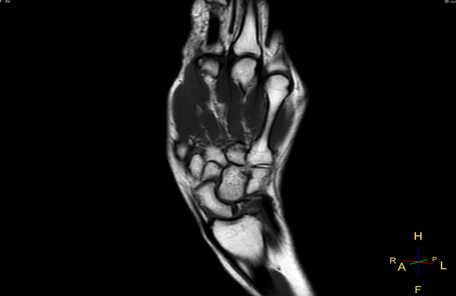
To demonstrate the feasibility for use as receiver clock, the wireless clock was merged with the optical fiber connected to the receivers in the mobile station, thus exchanging the original system clock with the recovered clock. Phantom images were acquired with both, the wired and the wireless clock, and analysis revealed no significant difference or phase artifacts. Figure 4 shows a wrist image taken with this final setup.
Conclusions
By applying round trip carrier phase tracking, the phase error on the recovered clock can be reduced to levels that meet the stringent requirements for digital MRI receivers.Acknowledgements
No acknowledgement found.References
- Patent Application, WO2017103759 A2, Systems and Methods for Wireless Communication for Magnetic Resonance Imaging (MRI) Systems.
- Lu J, Stang P, Robb F, Pauly, and Scott G, Wireless Clock Transfer for MRI Phase Correction, Proc. Intl. Soc. Mag. Reson. Med. 25 (2017), 2692
- Scott G, Robb F, Pauly J, and Stang P, Software Synchronization of Independent Receivers by Transmit Phase Tracking, Proc. Intl. Soc. Mag. Reson. Med. 25 (2017), 4311.
- Bosshard JC, and Wright SM, Phase Correction with Asynchronous Digitizers, Proc. Intl. Soc. Mag. Reson. Med. 23 (2015), 1787.
- Reber J, Marjanovic J, Schildknecht C, Brunner DO, and Pruessmann KP, Correction of Gradient Induced Clock Phase Modulation for In-Bore Sampling Receivers, Proc. Intl. Soc. Mag. Reson. Med. 25 (2017), 1056.
- Sekiguchi T, Akita K, Nakanishi T, Kato S, Adachi K, and Okamoto K, Development of Digital Wireless Transceiver for a MRI Coil with Clock Synchronization, Proc. Intl. Soc. Mag. Reson. Med. 17 (2009), 3048.
- Poincaré H, Halsted GB: The principles of mathematical physics. n.p.,1905.
- Einstein, A. , "Zur Elektrodynamik bewegter Körper"(PDF), Annalen der Physik, 17 (10): 891–921, (1905).
- Aggarwal K, Joshi KR, Rajavi Y, Taghivand M, Poon ASY, Pauly JM, and Scott G, Wireless MRI system using mm-Wave Transmission, Proc. Intl. Soc. Mag. Reson. Med. 24 (2016), 0545.
Figures
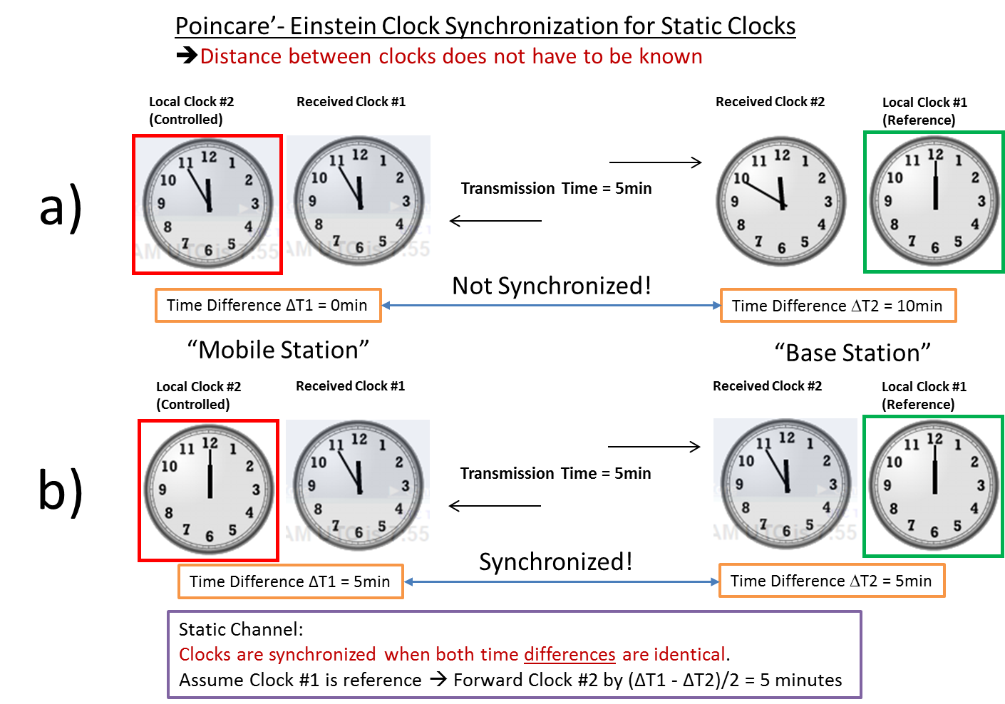
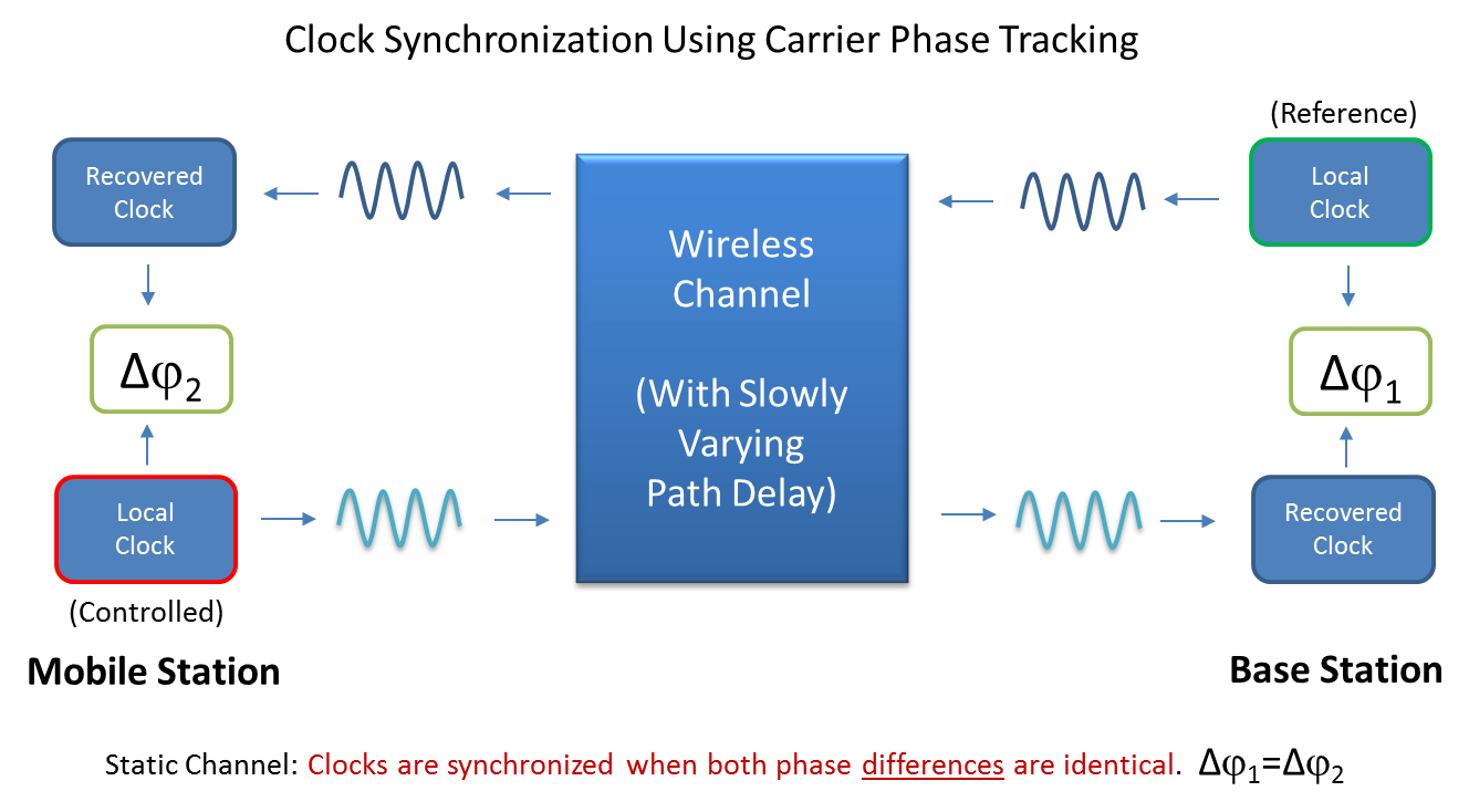
Figure 2: Basic principle of clock synchronization via carrier phase tracking. The terms "phase" and "time" relate to the same quantity for a given frequency. Therefore, measurement of time difference can be replaced by measurement of phase difference.
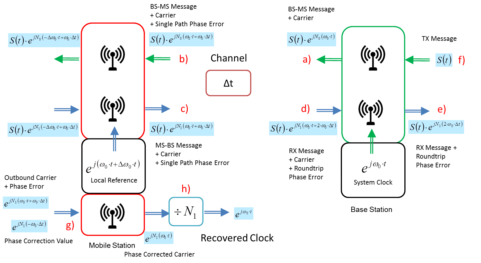
Figure 3: Detailed concept of clock recovery via carrier phase tracking: a) Base station sends message S1(t) modulated onto carrier N0·ω0·t. b) Mobile station recovers message S1(t) and carrier N0·ω0·(t+ Δt). c) Mobile station sends message S2(t) modulated onto carrier N1·ω0 ·(t+Δt) . d) Base station recovers message S2(t) and carrier N1·ω0(t+2·Δt) . e) Base station determines round trip phase error 2·ω0·Δt . f) Base station sends phase correction information -ω0·Δt to mobile station . g) Mobile station uses phase correction information -ω0·Δt to create a phase corrected carrier N1·ω0·t . h) Carrier is frequency divided by N1 to recover clock signal ω0·t
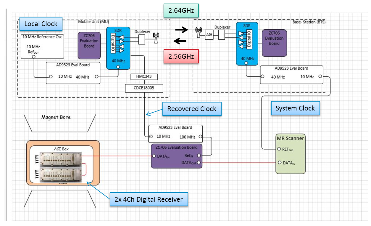
Figure 4: Block diagram of hardware and system connect