0026
Demonstration of a new volumetric wireless coil for extremities imagingAlena Shchelokova1, Dmitry Dobrykh1, Stanislav Glybovski1, Mikhail Zubkov1, Ekaterina Brui1, Cornelis A.T. van den Berg2, Irina Melchakova1, and Pavel Belov1
1Department of Nanophotonics and Metamaterials, ITMO University, Saint Petersburg, Russian Federation, 2Centre for Image Sciences, University Medical Center Utrecht, Utrecht, Netherlands
Synopsis
We demonstrate experimentally a new design of self-resonant tunable volumetric wireless coil based on a periodic array of coupled split-loop resonators. The wireless coil operates via inductive coupling with a birdcage coil enhancing the sensitivity of the latter at 1.5T and can be used for extremities imaging. Phantom and in-vivo wrist imaging with the proposed coil demonstrate 8.6 times higher transmit power efficiency in comparison with the birdcage coil and up to 2 times higher SNR versus standard receive-only coil.
Introduction
Wireless coils (WLCs), i.e. passive resonators inductively coupled to external Tx- and/or Rx-coils provide a useful tool in RF-coil design.1-4 WLCs locally increase the power efficiency of external Tx-coils simultaneously enhancing the sensitivity of external Rx-coils. Further improvement of WLCs consists in designing resonators providing high field homogeneity, low losses and safety. Recently developed metamaterial-inspired structures5-8 demonstrated new degrees of freedom in WLC design. These structures served as surface coils with a field-of-view confined to their planes. However, for many clinical applications, it is essential that magnetic field is uniform throughout the entire volume of the region-of-interest. In the present study, we describe and test on a phantom and in-vivo a novel volumetric WLC for wrist imaging at 1.5T that consists of periodic inductively coupled split-loop resonators (SLRs) made of telescopic brass tubes for precise tuning to 63.8MHz. It was shown numerically and experimentally that the proposed coil combined with a Tx/Rx-birdcage coil (BC) is a good alternative to the standard cable-connected Rx-coils in terms of transmit power, SNR and safety.Methods
Figure 1a shows the WLC design that consists of 20 isolated SLRs. Every SLR contains two parallel telescopic brass tubes of slightly different diameters sliding one against another. Two tubes are connected to each other at the ends by two structural capacities implemented as overlapping copper strips printed on the opposite sides of a 0.5mm-thick dielectric substrate with ɛ=3.38 and loss tanδ=0.0025. The structure resonant frequency can be tuned to 63.8MHz by adjusting the length of the tubes to L=273mm (Figure 1b). To enable inductive coupling with an external BC at least one of the B1 components must be normal to the plane of the SLRs. Electromagnetic simulations were done using a human model and realistic BC geometry in CST Microwave Studio 2016. MR-images were acquired on Siemens Magnetom Espree 1.5T MRI system using standard gradient echo and spin echo sequences. The BC was used both in Tx- and Rx-modes and the RF-power level was manually adjusted to ensure the same actual flip angle providing the maximum signal. Reference in-vivo images were acquired using a four-channel Rx-only flex-coil, which has similar dimensions as the WLC. The SNR was calculated by dividing a mean value of the signal from the region-of-interest by the standard deviation of noise in a signal-free region. No parallel imaging was applied.Results
Figure 1с demonstrates the homogeneously distributed magnetic near-field profile of the eigenmode of the WLC in the region-of-interest. Note, the electric field is mostly confined inside the structural capacity. Figure 2 shows numerically calculated and experimentally measured B1+-maps for a phantom placed inside the BC without and with the WLC. The B1+ distribution in the phantom is homogeneous even after focusing by the WLC and increased by 8.6 times for the same Tx power according to measurements. The results of numerical simulations with a realistic body model in the presence and the absence of the WLC are given in Figure 3. The increase of the homogeneously distributed B1+ in the region-of-interest was found to be a factor of 5.3. At the same time, the maximum 10g SAR in the whole body model is approximately the same for the cases with and without the WLC while the local maximum in the wrist area is approximately 1.5 times higher in the presence of the WLC (Figure 4a,b). However, the SAR for the same B1+=0.3uT in the region-of-interest becomes 30 times lower with the WLC since the required power reduces from 1W to 0.021W (Figure 4c). It means that achieving the same actual flip angle with the WLC is even safer than with the BC alone in terms of the maximum local SAR. Figure 5 shows the coronal MR-images from the wrist of two healthy volunteers. The transmitter voltage was at least 6.7 times lower in all the scans with the WLC. The SNR enhancement with respect to the flex-coil of 24% was achieved for gradient echo sequence in supine position and 100%– for spin echo sequence in “Superman” position while keeping image homogeneity in the region-of-interest and introducing no artifacts with the WLC.Conclusions
It has been for the first time demonstrated that a WLC might show a similar performance as a cable-connected coil of similar dimensions in terms of imaging quality and safety. The same design can be adjusted by varying geometric parameters of capacitive traces, substrate permittivity and thickness in order to change the region-of-interest or the Larmor frequency. Thereby, the proposed WLC could be adapted for other MRI tasks at 1.5T or higher fields.Acknowledgements
This work was supported by the Ministry of Education and Science of the Russian Federation (Zadanie No.3.2465.2017/4.6). The authors thank Prof. Constantin Simovski, Prof. Sergey Tretyakov, Dr Nikolai Avdievitch and Dr Alexey Slobozhanyuk for useful discussions, Dr Vladimir Fokin, Dr Alexander Efimtcev, Mr Andrey Sokolov, Mr Dmitry Dmitriev, and Dr Alexander Kozachenko for assistance with MRI experiments.References
1. Shigehiro H, et al. Application of inductively coupled wireless radio frequency probe to knee joint in magnetic resonance image. J. Syst. Cybern. Informatics. 2009;7(5):6-10. 2. Shumin W, et al. B1 homogenization in MRI by Multilayer Coupled Coils. IEEE Trans. Med. Imaging. 2009;28:551-554. 3. Bulumulla S, et al. Inductively coupled wireless RF coil arrays. Magn. Reson. Imaging. 2015;33:351-357. 4. Ludwig U, et al. Dental MRI using wireless intraoral coils. Sci. Rep. 2016;6:23301. 5. Slobozhanyuk A P, et al. Enhancement of Magnetic Resonance Imaging with Metasurfaces. Adv. Mater. 2016;28:1832-1838. 6. Schmidt R, et al. Flexible and compact hybrid metasurfaces for enhanced ultra high field in vivo magnetic resonance imaging. Sci. Rep. 2017;7:1678. 7. Shchelokova A, et al. Wireless coil based on meta-technologies for MRI implementations. Proc. Intl. Soc. Mag. Reson. Med. 2017;25,0761. 8. Saha S C, et al. Evaluation of a metasurface resonator for in vivo imaging at 1.5T. Proc. Intl. Soc. Mag. Reson. Med. 2017;25,2702.Figures
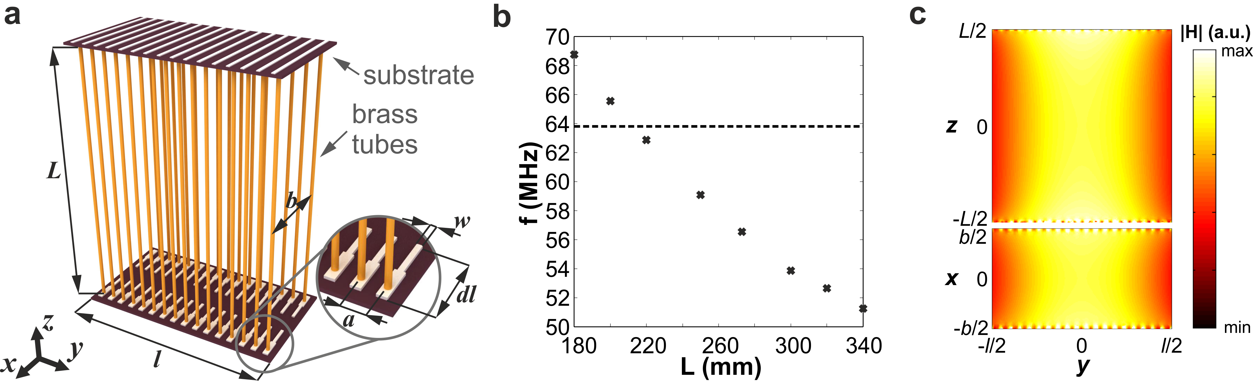
Figure 1. (a) Schematic view of the wireless coil based on an array of 20 split-loop resonators (SLRs). Each SLR formed by two parallel brass tubes with adjustable length L spaced b=100mm apart and connected from both sides through capacities printed on a dual-layered substrate with the length l=244mm. The inset demonstrates zoomed view of capacitive traces: w=2.65mm, dl=55.33mm, a=12mm. (b) Numerically calculated dependence of the coil fundamental eigenmode resonance frequency (f) on the length of the tubes (L). (c) Numerically calculated magnetic field amplitude in the zy- and xy-planes inside the coil at the eigenmode resonance.
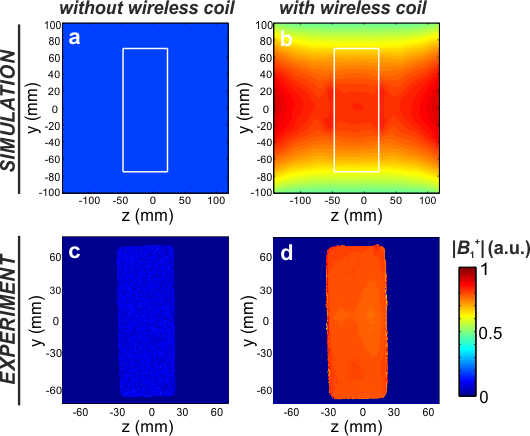
Figure 2. Numerically calculated |B1+|-maps
for a rectangular phantom with relative permittivity 34 and conductivity 0.4S/m
placed inside a birdcage coil without (a) and with the wireless coil (b)
normalized to 1W of total accepted power. White solid lines indicate the
boundaries of the phantom. Experimentally measured normalized |B1+|-maps
for a homogeneous phantom filled with NiSO4 doped water inside a
birdcage coil alone (c) and in the presence of the wireless coil (d). The
gradient echo sequence parameters: FOV 180x180mm2, matrix size =
256×192, TR/TE=1010/13.5ms.
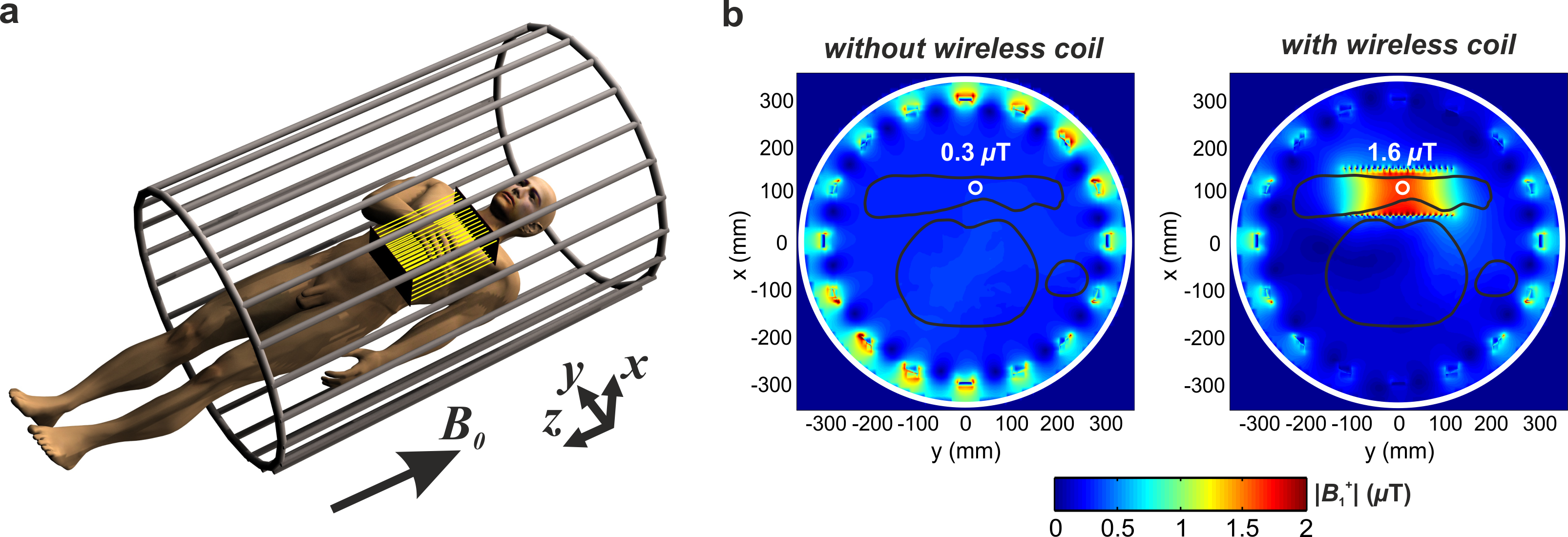
Figure 3. (a) Schematic view of the position of a human inside the birdcage coil with a wrist inside the wireless coil. (b) Numerically calculated |B1+|-maps for a human voxel model placed inside the birdcage coil without (left) and with (right) the wireless coil for 1W of total excitation power. Black solid lines depict a human body and hand’s contours. White circles indicate the field magnitude at the center of the wrist equal to 0.3uT without and 1.6uT with the wireless coil. White solid lines indicate boundaries of the birdcage coil.
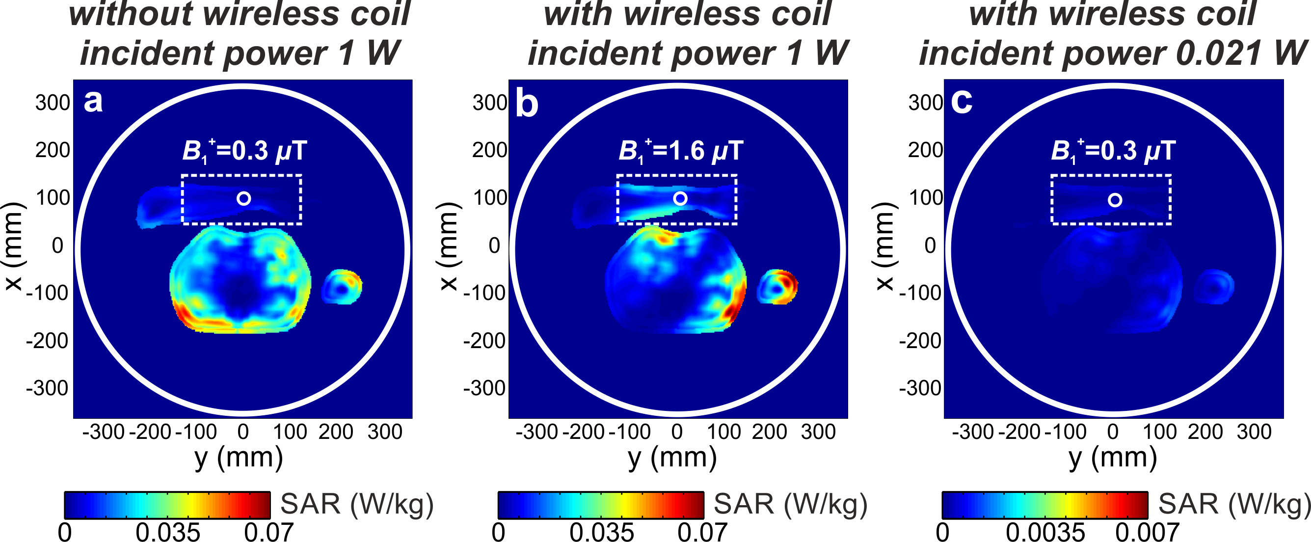
Figure 4. Numerically calculated 10g SAR maps for a human voxel model placed inside the birdcage coil for three cases:
(a) without the wireless coil for 1 W accepted power (B1+=0.3uT
in a wrist center); (b) with the wireless coil for 1W accepted power (B1+=1.6uT
in a wrist center); (c) with the wireless coil for 0.021W accepted power (B1+=0.3uT
in a wrist center). White dashed lines show boundaries of the wireless coil; white solid lines indicate boundaries of
the birdcage coil.
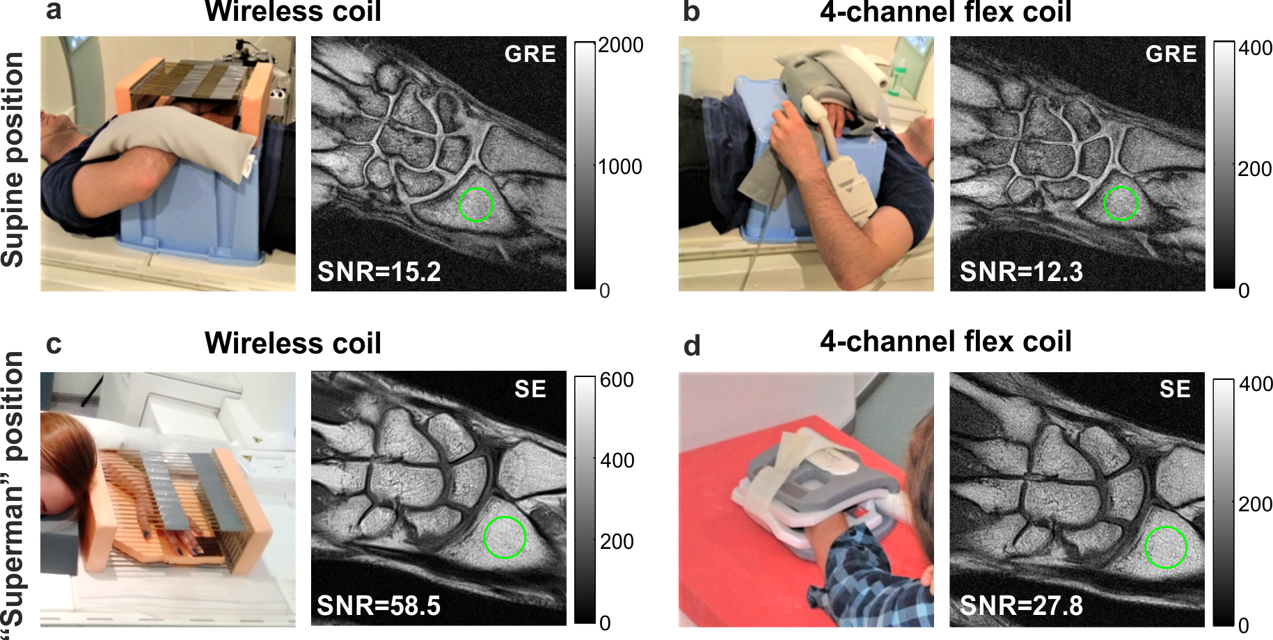
Figure 5. Photographs of the in-vivo setups and MR images of the
wrist acquired (a) with the wireless coil together with the Tx/Rx-birdcage coil
and (b) Rx-only flex-coil and Tx-birdcage coil using gradient echo (GRE)
sequence in supine position; (c) with the wireless coil together with the Tx/Rx-birdcage
coil and (d) Rx-only flex-coil and Tx-birdcage coil using spin echo (SE)
sequence in “Superman” position. Green circles correspond to the area where
signal values were calculated. The imaging parameters for GRE sequence: TR/TE
417/9.53ms, FA 700, 256x256 matrix, FOV 120x120mm2, for
SE: TR/TE 644/17ms, FA 900, 256x256 matrix, FOV 90x90mm2.