0025
Pilot Tone Software Synchronization for Wireless MRI Receivers1Electrical Engineering, Stanford University, Stanford, CA, United States, 2Stanford University, Stanford, CA, United States, 3GE Healthcare, Aurora, OH, United States, 4Procyon Engineering, San Jose, CA, United States
Synopsis
For wireless MRI to become a reality, methods must be developed to synchronize receivers that have no physical connection to the scanner. Here, we demonstrate that dual pilot tones are needed to correct for both timing skew and frequency offsets. Bench tests were performed with a master and free running slave receiver, in which the images were re-synchronized by frequency estimation methods on pilot tones.
Introduction
Because of the cabling challenges associated with high channel count receive arrays, a major goal of MR engineering has been the development of wireless receive arrays. Wireless coil technology could enhance recent trends to develop wearable receive arrays. However, many challenges exist to make wireless MRI receive arrays a reality, including low power electronics, wireless power delivery, wireless data transfer, wireless triggering and wireless phase synchronization. Here, we present dual pilot tone methods to perform time shift and phase/frequency offset correction if receive arrays use free running clocks that are not synchronized to the MRI system.
Theory
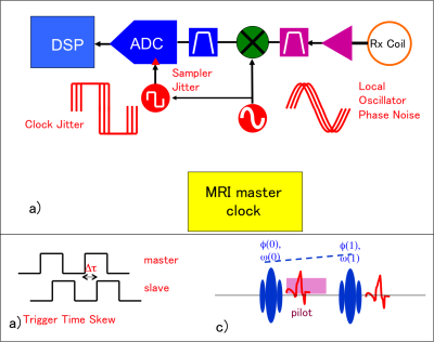
If the receiver system employs a free-running clock, phase and frequency errors will be embedded in the data (Fig. 1a). Second, because the local clock time will not match that of the scanner, there will always be a time delay between an event trigger on the scanner, and its recognition on the slave device, leading to a time skew. Both of these issues can be detected and corrected by embedding dual frequency pilot tones during the readout interval (c). A single tone of known frequency [1,2] can be used to frequency and phase correct data. With the second tone of known frequency difference from the first, the measured phase difference allows computation of the time skew by $$$ \delta t = \delta \phi / \delta \omega $$$. To extract the dual tone frequency and phase parameters, Quinn's 3 sample frequency estimator is used. This estimator yields results very close to the Cramer-Rao lower bound for maximum likelihood estimators.Methods
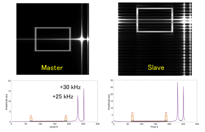
To demonstrate this approach, we used two Medusa consoles, one acting as a Master MRI control system, and the second as a free running slave device operating from a separate crystal oscillator. The master generates both MRI RF pulse sequence signals and synthetic k-space data of a "box" phantom. This image was chosen to allow easy detection of reconstruction ghosts. A phase locked pair of pilot signals offset by 30 kHz and 25 kHz from the 64 MHz center frequency provided the synchronization signals. Figure 2 shows the images of the Master and Slave channels with the pilot tones present. The k-space projections are also shown to indicate pilot tone levels. Note that the pilots do not fall exactly into a DFT frequency bin, causing spectral leakage. The Quinn estimator depends on this for frequency estimation.
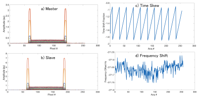
In Figure 3, the frequency and phase estimates of each pilot tone are subtracted from the data. In the case of the master, since the pilot frequency are known exactly, only the phase offset was needed for subtraction. For the slave data, the Quinn estimator was used. In both cases, it appears as if the pilots have been removed. This means the phase estimates are also accurate.
Results
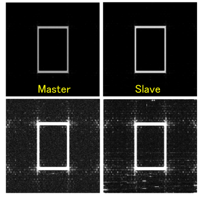
The pilot phase, and frequency offsets allow both frequency offset and time skew to be computed (Fig 3). The time skew is shown as fraction of the sample cycle and is sawtooth-like because the slave will roll into and out of time sync. The frequency estimates are accurate to sub Hz levels. The final recovered slave image is shown in Figure 4 at normal windowing levels and at high scaling to reveal noise floor residual errors. This can be compared with a master data set that did not include embedded pilots. There is no gross ghosting in the re-synchronized image, but some extra RF interference remains at low levels.Discussion
The pilot tone approach is an alternative to using the transmit waveform for software synchronization. A key issue, however, is ensuring that the signal levels do not cause interference or raising of the fundamental image noise floor. The primary issue is the phase noise of the pilot, which is a form of unconverted 1/f noise. The frequency estimators allowed subtraction of the the ideal numerical sinusoid, but cannot subtract the phase noise associated with any physical oscillator. A second issue arises if one attempt to use the pilot for sample by sample phase correction. This can work well if the pilot SNR is above the peak k-space SNR, but does not necessarily correct for time skew as an ambiguity exists between time shift of a sinusoid and a phase shift.Conclusion
At least two pilot tones are needed to remove the ambiguity between a true trigger timing error, and a sinusoid phase shift. With frequency estimator methods, the recovered images can be of high quality. Software synchronization of wireless receivers is completely tractable using pilot tones or transmit signal sampling methods.Acknowledgements
NIH R01EB019241, GE Healthcare Research GrantReferences
[1] J. Bosshard, Phase Correction with Asynchronous Digitizers, 23rd ISMRM, 2015.
[2] G. Scott, Synchronization of Wireless Transmitted MRI Signals in MRI System, US7,123,009, 2005.
[3] B. Quinn, Estimation of Frequency, Amplitude and Phase from the DFT of a Time Series, IEEE Trans. Sig. Proc. 45, p814-817, 1997.
Figures


