0024
Comparison of a 16-channel monopole/dipole hybrid array with a combined 8-channel monopole + 8-channel high dielectric constant (HDC) disk dipole array for head imaging at 10.5TMyung Kyun Woo1, Lance DelaBarre1, Jerahmie Radder1, Russell Lagore1, Yigitcan Eryaman1, Kamil Ugurbil1, and Gregor Adriany1
1Center for Magnetic Resonance Research, Minneapolis, MN, United States
Synopsis
We evaluate the performance both in simulation and experiment of two 10.5T head transceiver arrays. The first is a 16-channel monopole/dipole hybrid array (called the Mono-Dipole array for brevity). The second is a 16-channel monopole/HDC disk dipole array. (A combination of two 8-channel arrays: a monopole array and a high dielectric constant (HDC) disk dipole array). These novel coil designs were compared against a standard 16-channel stripline array to elucidate their relative benefits and drawbacks.
Introduction
As a transmitter, a 16-channel dipole head array is desirable above 7T, however, it is difficult to achieve this high channel count due to coupling [1-3]. It is also necessary to shorten the dipole for human head applications [4, 5]. Here we examine the performance of two new 10.5T array designs based on dipole and monopole antenna arrays. The first type is a 16-channel monopole/dipole hybrid array (Mono-Dipole, for brevity) and the other is a 16-channel Monopole + HDC Disk Dipole array which is an array combination consisting of an 8-channel monopole antenna array with an 8-channel dipole array that employs high dielectric constant (HDC) disk substrates [6]. We first compared the 8-channel arrays of dipole, Mono-Dipole, and monopole in simulation and later verified those experimentally. We then compare transmit efficiency of the 16-channel Mono-Dipole head array, the 16-channel Monopole + HDC Disk Dipole array, and a 16-channel close-fitting stripline array.Methods
Schematics and pictures of the 16-channel transceiver head arrays are shown in Figure 1. The 16-channel Mono-Dipole array (24 cm diameter and 12 cm length) has sixteen equally spaced dipole antennas, and one leg of each dipole antenna was effectively shortened to a common ground using 680 pF capacitors. The length of each leg of the dipole is 12 cm. Two floating copper shields (3.5 cm x 22 cm in size) were placed between one of the poles of the antenna along the z-direction to extend the longitudinal field of view [7]. Each shield was spaced 1 cm away from the center of the pole and placed 2 cm away from the feed point. Floating cable traps were used to suppress the cable sheath currents [8]. For the 16-channel Monopole + HDC Dipole array (24 cm ID x 12 cm L), the longitudinal coverage was extended with a dual row approach by combining the 8-channel monopole array with the 8-channel HDC disk dipole array (8 cm diameter by 1.6 cm thick disks, σ= 0.0031 S/m and εr = 101.05). The 8-channel HDC disk dipole array was placed 22.5° radially offset from the monopoles and the longitudinal gap between the HDC dipoles and the monopole ground plane was 10 cm. Noise correlation matrices of the arrays were obtained to evaluate crosstalk between elements (Figure 2). Transmit B1+ profiles were obtained on a cylindrical phantom (8.5 cm radius and 30.5 cm height) using an AFI sequence. The phantom has uniform electrical properties (σ= 0.6 S/m, εr = 49). Electromagnetic simulation (XFdtd; REMCOM, State College, PA) was performed to calculate the B1+ field. The performance of the Mono-Dipole array was initially compared with 8-channel arrays of dipoles, the monopoles, and the Mono-Dipoles (Figure 3). A phantom with matching dimension and electrical properties was selected for experimental verification with a 2 x 2 x 2 mm3 resolution with B1+ normalized to 1 W power. The experimental results of the comparison between the Mono-Dipole, Monopole + HDC Dipole, and stripline arrays is shown in Figure 4 and z-directional profile of B1+ efficiency is shown in Figure 5.Results and Discussion
The 16-channel Mono-Dipole array consistently showed good decoupling as indicated in Figure 2 (10-14 dB between neighboring elements). Good agreement between simulation and experiment ~10% was achieved for the highest B1+ values among the 8-channel dipole, monopole, and Mono-Dipole arrays. The transmit efficiency of the stripline array (0.52 µT/sqrt (W)) was higher than the Mono-Dipole array (0.29 µT/sqrt (W)). In part, this difference may be attributed to the smaller dimensions of the stripline (20% smaller area) in comparison to the Mono-Dipole. Without the floating shields on the Mono-Dipole (used to expand the coverage) the efficiency improves and is similar to that of the stripline, at the cost of a narrower field of view. For the 16-channel Monopole + HDC Dipole array, B1+ efficiency (0.43 µT/sqrt (W)) is higher than the 16-channel Mono-Dipole head array, however, this value is lower than the 8-channel monopole array (0.79 µT/sqrt (W)).Conclusion
For head applications, it is difficult to achieve sufficient dipole decoupling due to the greater relative distance from the element to tissue. By connecting one leg of each dipole, we effectively created a radial ground plane resulting in a hybrid monopole/dipole array. Greater decoupling is observed in the 16-channel Mono-Dipole array compared to a comparable 16-channel dipole array. Furthermore, this array has greater whole head cover at 10.5T than other coil designs examined. In future work, we hope to improve the performance of the 16-channel Monopole + HDC dipole array.Acknowledgements
NIH- U01 EB025144 S10 RR026783, BTRC P41 EB015894, P30 NS076408 and WM Keck FoundationReferences
[1] Ian Robert Oliphant Connell, Ravi S Menon. Decoupling and Integration of Electric Dipoles into RF Arrays. In Proceedings of the 25th Annual Meeting of ISMRM, Honolulu, 2017. p. 4295 [2] Kyle M Gilbert, Joseph S Gati, L Martyn Klassen, Stefan Everling, Ravi S Menon. Fifteen-channel receive coil for high acceleration rates in UHF marmoset imaging. In Proceedings of the 25th Annual Meeting of ISMRM, Honolulu, 2017. p. 2661 [3] Riccardo Lattanzi, Graham C. Wiggins, Bei Zhang, Qi Duan , Ryan Brown, Daniel K. Sodickson. Approaching Ultimate Intrinsic Signal-to-Noise Ratio With Loop and Dipole Antennas. Magn Reson Med DOI: 10.1002/mrm.26803, 2017 [4] Gang Chen, Christopher M. Collins, Daniel K. Sodickson, and Graham C. Wiggins. A Method to Assess the Loss of a Dipole Antenna for Ultra-High-Field MRI. Magn Reson Med DOI 10.1002/mrm.26777, 2017 [5] Gang Chen, Martijn Cloos, Daniel Sodickson, Graham Wiggins. A 7T 8 channel transmit-receive dipole array for head imaging: dipole element and coil evaluation. In Proceedings of the Joint Annual Meeting of ISMRM-ESMRMB, Milan, 2014. p. 621 [6] Russell L Lagore, Lance DelaBarre, Qing X Yang, Michael Lanagan, Yigitcan Eryaman, Sebastian Rupprecht, Wei Luo, Byeong-Yeul Lee, Xiao-Hong Zhu, Kamil Ugurbil, Wei Chen, Gregor Adriany. In Proceedings of the 25th Annual Meeting of ISMRM, Honolulu, 2017. P. 1128 [7] Myung-Kyun Woo, Suk-Min Hong, Jongho Lee, Chang-Ki Kang, Sung-Yeon Park, Young-Don Son, Young-Bo Kim, Zang-Hee Cho. Extended Monopole Antenna Array with Individual Shield (EMAS) Coil: An Improved Monopole Antenna Design for Brain Imaging at 7 Tesla MRI. Magn Reson Med 75:2566–2572, 2016 [8] D.A. SEEBER, J. JEVTIC, A. MENON. Floating Shield Current Suppression Trap. D.A. Concepts Magn Reson Part B Magn Reson Eng 21B: 26–31, 2004Figures
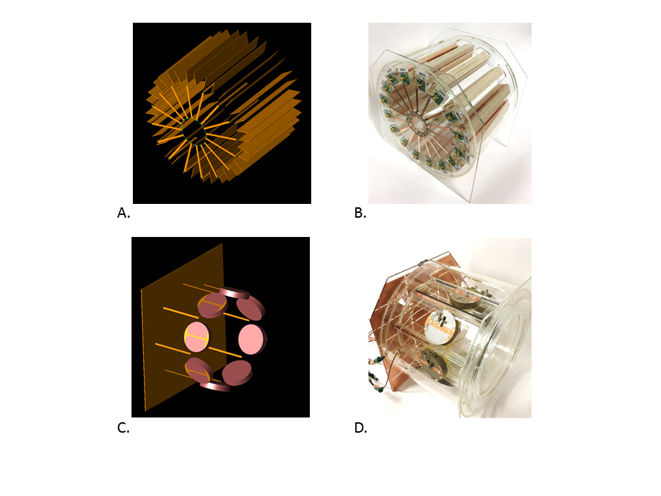
Figure 1. A, B
: Schematics and Picture of the
16-channel Mono-Dipole array.
C, D:
Schematics and Picture of
the 16-channel
Monopole + HDC Dipole array
(an 8-channel Monopole
array
+ an 8-channel HDC
Dipole array)
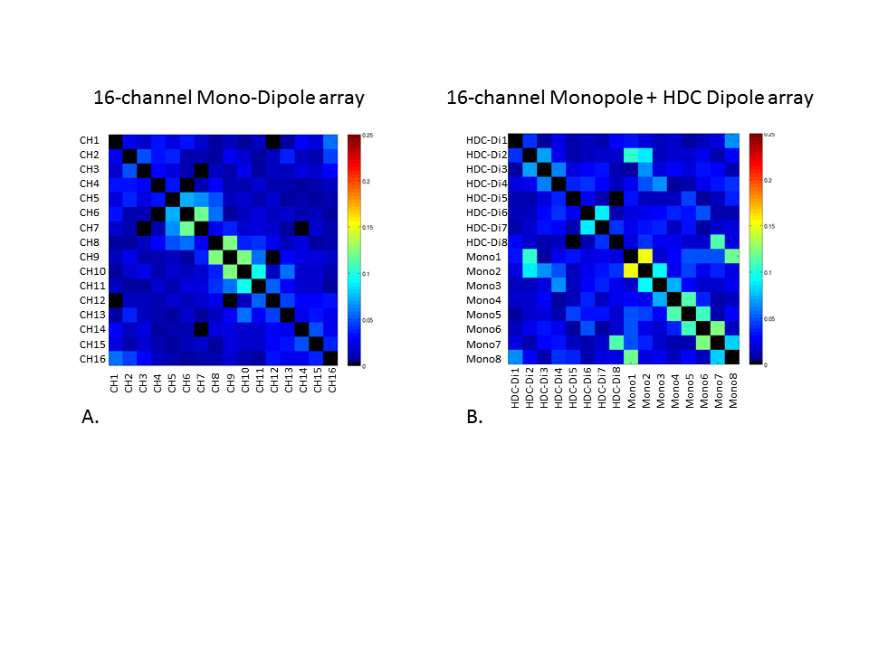
Figure 2.
Noise
correlation
matrix of A:
16-channel Mono-Dipole arrays and B: 16-channel Monopole + HDC Dipole array
(an 8-channel Monopole
arrays
+ an 8-channel HDC
Dipole array).
The
16-channel Mono-Dipole array
shows excellent
correlation
values (less than 0.12) regardless of close distance (2cm) among elements.
For the
16-channel Monopole + HDC Dipole array, low correlation (less than 0.08) is
observed between 8-channel
HDC dipoles
(Distance between elements: 6.5cm) , however, relatively high correlation
(less than 0.15) is observed between monopoles. (Distance between elements: 8cm)
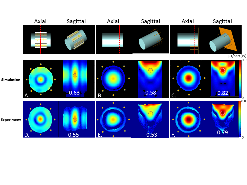
Figure 3.
Simulation
and Experimental B1+ maps
of 8-channel Dipole array
(Inner diameter:
19 cm) with teflon
blocks (εr = 2.2), 8-channel Mono-Dipole array
(Inner diameter:
24 cm) and 8-channel Monopole array (Inner diameter:
24 cm): Simulation data set of the axial and sagittal plane A: 8-channel
Dipole
array, B: 8-channel
Mono-Dipole
array, and
C: 8-channel Monopole array.
Experimental
data set of the
axial and transverse plane D: 8-channel Dipole array, E: 8-channel
Mono-Dipole
array, and F:
8-channel Monopole
array..
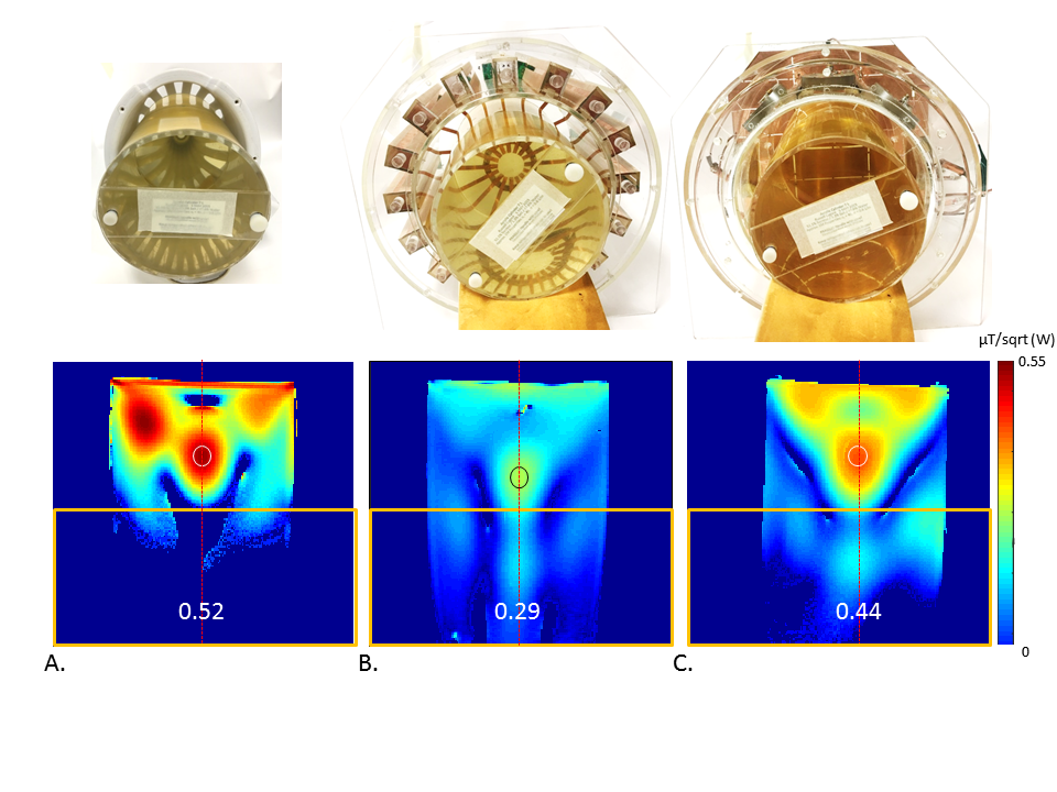
Figure 4.
Experimental B1+ maps
of A: 16-channel
stripline
array, B: 16-channel
Mono-Dipole
array,
and C:
16-channel Monopole + HDC Dipole array (an 8-channel monopole
array
+ an
8-channel HDC
dipole array)
on the
axial and transverse plane. The
profile of red line is indicated on Figure 5. Yellow
boxes means the increased coverage for the human head imaging.
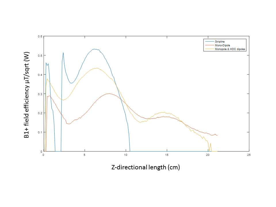
Figure 5. B1+
field profile of
the 16-channel Mono-Dipole array, the 16-channel Monopole
+ HDC Dipole array
(an 8-channel Monopole
array
+ an
8-channel HDC Dipole
array)
and the 16-channel
stripline
array.