0023
New ferroelectric ceramics for transmit efficiency enhancement at 1.5 Tesla1Radiology Department, C.J. Gorter Center for High Field MRI, Leiden University Medical Center, Leiden, Netherlands, 2Department of Nanophotonics and Metamaterials, ITMO University, Saint Petersburg, Russian Federation, 3Giricond Research Institute, Ceramics Co., Saint Petersburg, Russian Federation
Synopsis
The presence of medical implants often results in MR scans with low SAR being prescribed, which reduces the diagnostic quality of the images. This work shows that one can achieve an increase in local transmit efficiency and a corresponding decrease in SAR at 1.5 Tesla using new ferroelectric materials (based on BaTiO3 with ZrO2 and CeO2-additives) with relative permittivities higher than 4500. Simulations and phantom/in vivo experiments show an increased local transmit efficiency of ~50% from the body transmit coil, with a corresponding increase in SNR for a given value of SAR.
Introduction
To perform MRI scans on patients with implants it is often required to substantially reduce the RF power and specific absorption rate (SAR), resulting in poor image quality. In cases where the imaging ROI is different from the area in which the medical device is implanted, high permittivity (er = 300-3000)1,2 materials can be placed around the imaging ROI at 3T to concentrate the local transmit field from the body coil3. For operation at 1.5T even higher permittivities are needed, requiring the design and testing of new types of materials. Here we propose and evaluate ferroelectric materials based on BaTiO3 with ZrO2 and CeO2-additives with relative permittivities higher than 4500.Methods
Electromagnetic simulations were performed in CST Microwave Studio 2016. Ferroelectric blocks of dimensions 71x57x13 mm were produced with εr=4500 and σ=1.79 S/m (confirmed using network analyzer measurements). The blocks were designed as follows: pre-synthesized BaTiO3 (HPBT-1) (Fuji Titanium Industry Co., Japan) with Ba/Ti =0.996 mol. ratio and high purity ZrO2 and CeO2-additives were mixed in the required proportions in a vibration mill for 3 h. Samples of the required geometrical shape and size were prepared by hydraulic pressing; 10% solution of polyvinyl alcohol was taken as a binder. The samples were sintered in air at a temperature of 1340 0C (3 h) in a chamber electric furnace until zero water absorbance and porosity less than 4% was obtained. All MRI measurements were performed on a Philips Ingenia 1.5 T system (Leiden University Medical Center, Leiden, The Netherlands). Four high permittivity blocks were placed around a tissue-mimicking phantom and also the wrist of a volunteer. The body coil was used to transmit and an eight-element phased array to receive. B1+ enhancement was evaluated using a series of rapid low-tip angle gradient-echo images with varying tip angle. Wrist images were obtained with a T1 weighted TSE sequence: TR=776 ms, TE=18 ms, FA=900, FoV=110x140 mm and 2 mm slice thickness.Results
Figure 1 shows simulated B1+ map on a cylindrical phantom with and without blocks. The enhancement in the center of the phantom in the transmit efficiency is approximately 40%. The dependence of the received MR signal on the tip angle is shown in Figure 2.Figure 3 shows a photograph of the in-vivo measurement setup, as well as T1-weighted coronal images of the wrist without and with ferroelectric material in place. The images were acquired with the same input power applied to the body coil. Figure 4 shows a plot of a signal intensity along the red line shown in Fig. 3. From the intensity plot it is seen that an increase of 50% in signal intensity (for the same applied power) is achieved.
Discussion
In order to enhance the local transmit efficiency at 1.5 T one has to design materials with very high permittivity and relatively low loss in order to produce high displacement currents and low conductive currents in the dielectric. The material considered in this work was BaTiO3 with ZrO2 and CeO2-additives. The placement of non-resonant blocks, produced from such a material, around a wrist of volunteer increases the local transmit field by 50%, enabling a reduction in applied RF power.Conclusions
In cases where the imaging ROI is different from the location of the medical implant, the local transmit efficiency can be increased for 1.5 T imaging by using new materials with very high permittivity. These could also potentially be used to increase the receive sensitivity for surface applications, as has been demonstrated for lower permittivity materials at 3 T1.Acknowledgements
This work was funded by grant ERC NOMA-MRI, number 670629References
1. Rupprecht S, Sica CT, Chen W, Lanagan MT, Yang QX, Improvements of transmit efficiency and receive sensitivity with ultrahigh dielectric constant (uHDC) ceramics at 1.5 T and 3 T, Magn Reson Med. 2017 doi: 10.1002/mrm.26943.2. Koolstra K, Boernert P, Brink W, Webb A. Improved image quality and reduced power deposition in the spine at 3T using extremely high permittivity materials, Magn Reson Med. 2017 doi10.1002/mrm.26721/2017.
3. Yu Z.,Xin X., Collins C., Potential for high-permittivity materials to reduce local SAR at a pacemaker lead tip during MRI of the head with a body transmit coil at 3 T, Magn Reson Med. 2017;78: 383-386.
Figures
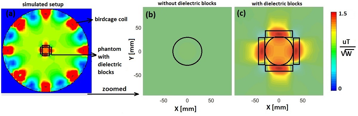
Figure 1. Simulated setup - phantom with dielectric blocks placed in a centre of a birdcage coil (a). Calculated B1+ maps at 63.8 MHz within the phantom without (b) and with (c) dielectric blocks. All the B1+ maps are scaled to 1 W input power.
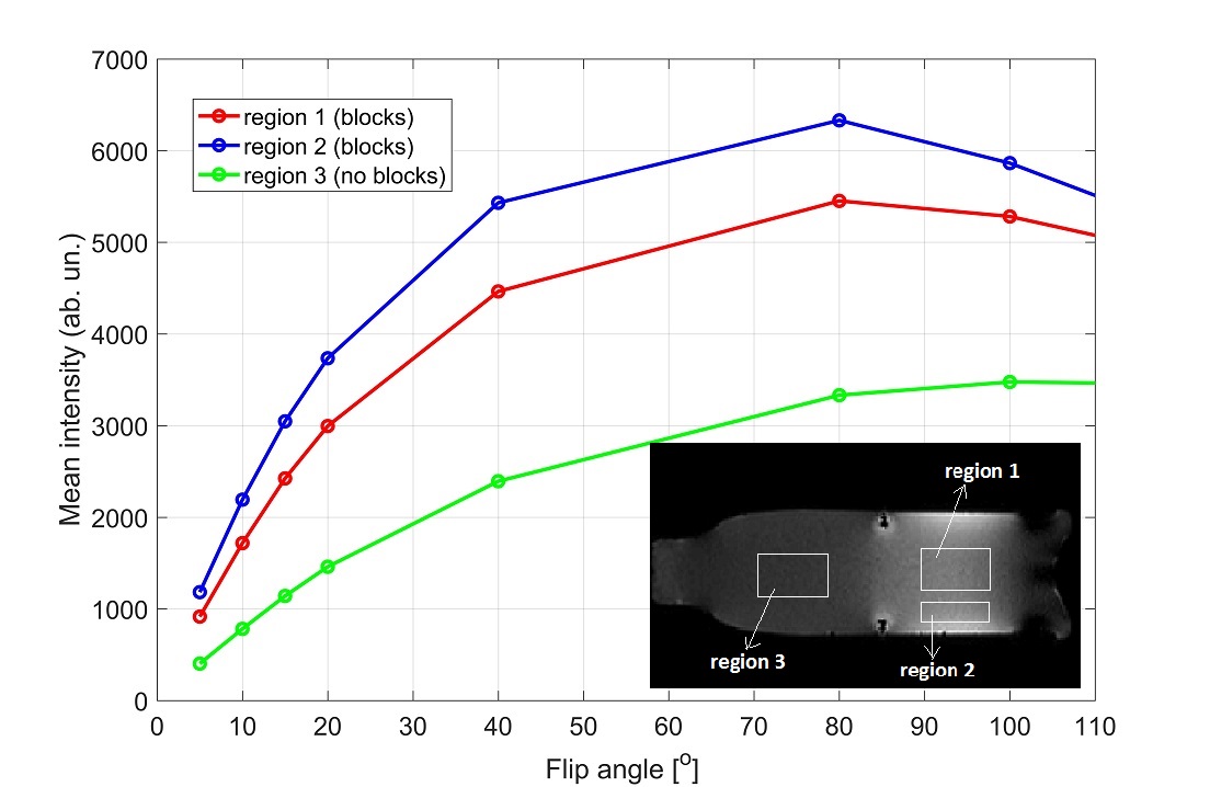
Figure 2. Measured signal intensity vs. tip angle in a cylindrical bottle phantom with high permittivity ceramic blocks placed around. The signal intensity was measured in three different regions – region 1 and 2 (in the proximity of the blocks) and region 3 (no influence of the blocks).
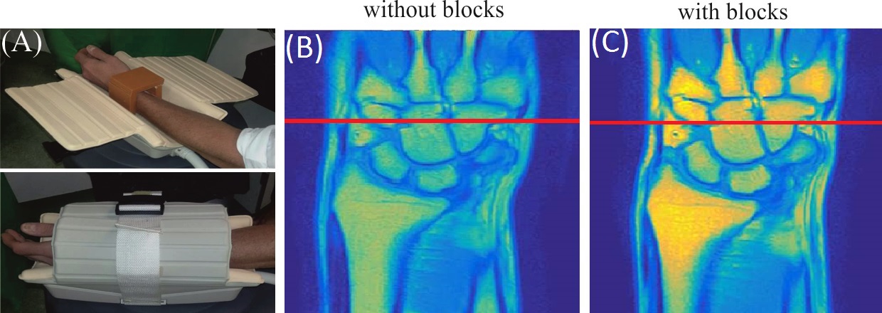
Figure 3. Photographs of in-vivo experimental setups with a volunteer, dielectric blocks placed around the wrist and receive coil (a).The T1 weighted wrist images without blocks (b) and with blocks (c). The intensity profiles plotted in Figure 4 are along a red line shown in (b) and (c).
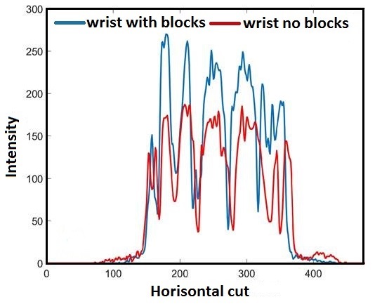
Figure 4. Intensity profile along a red line in Fig. 3(b) and Fig. 3(c). It is seen that signal enhancement is around 1.5 times in the presence of blocks.