0020
Custom, 3D Sprayed MRI receive coils1EECS, UC Berkeley, Berkeley, CA, United States, 2Georgia Institute of Technology, Atlanta, GA, United States, 3ME, UC Berkeley, Berkeley, CA, United States
Synopsis
We developed process for fabricating patient-specific MRI receive coils via scalable and adaptable additive manufacturing approaches. Process relies on spray-depositing solution-processed electronic materials onto 3D printed custom substrates. We conducted careful materials selection, process optimization and fabricated fully functional coils. The coils spray deposited onto spherical substrate demonstrated higher SNR than control coil, when evaluated using phantom of the spherical shape, due to superior conformability to the phantom. Our approach is poised to enhance high quality clinical imaging by ensuring optimum fit of the MRI receive coils to the body parts with complex geometries, enabling reproducible placing on the patient and eliminating motion artifacts.
Introduction
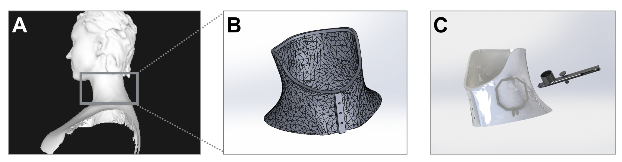
Design and positioning of receive coils are one of the key factors determining SNR of the MRI images. Particularly, placing coils in the close proximity to the body has been shown to significantly improve image quality (1-4). Commercial coils used in current clinical practice are not adapted to optimally fit every patient’s anatomy. This often results in substantial gap between receive coils and the body, which is detrimental to SNR.Additionally, further development of the next generation therapeutic approaches, such as MRI guided surgeries, relies on ability to conduct multiple, often time-consuming, procedures on the same patient. This requires addressing additional issues associated with utilization of conventional coils, such as restriction of motion and ability to position patient reproducibly. We address aforementioned limitations by developing process for fabricating patient-specific MRI receive coils. The process consists of scanning the patient using commercially available structure sensor (Fig. 1A), 3D printing the custom substrate for the body part of interest (Fig. 1B) and spray-depositing coil components onto custom printed 3D substrates by using solution processed electronic materials (Fig. 1C). Our approach enables scalable and adaptable additive manufacturing of patient-specific MRI coils, opening new pathway towards customization of MRI imaging.Methods
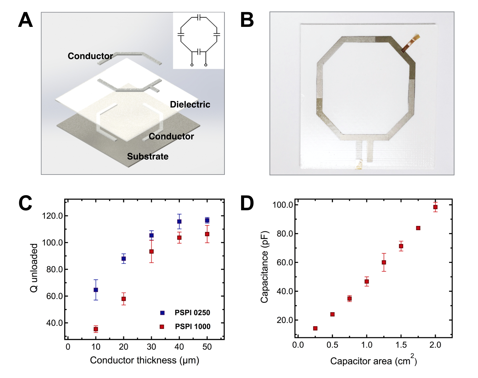
Careful selection of materials and fabrication approach is essential for achieving high quality custom MRI receive coils. Fig. 2A and 2B shows the schematics of the coil components and a photograph of the full coil spray deposited onto 2D substrate.Four-capacitor LC circuit is achieved by creating a pattern from two conductor layers with dielectric in-between (1). Spray-deposition was chosen for fabricating coil components, because it enables rapid deposition of a wide range of materials onto curvilinear surfaces. Carbon3D printing process and cyanide ester material were chosen to fabricate substrate. Cyanide ester is MRI transparent, heat and flame resistant material, which makes it a perfect candidate for using as a high quality substrate for MRI receive coils. Polystyrene was chosen as a dielectric due to low loss tangent factor, relatively high glass transition temperature of 100º C (preferred for curing silver) and ability to be processed from the solution. The polystyrene to solvent (toluene) ratio was adjusted to achieve optimum spray-deposition process.Silver ink from Novacentrix was used as a conductor due to relatively low curing temperature (below glass transition temperature of polystyrene), simple handling, good rheological properties and, importantly, water-based solvent. Solvent used in the conductor ink should not have affinity to polystyrene – to avoid shorting between top and bottom conductor traces.Results
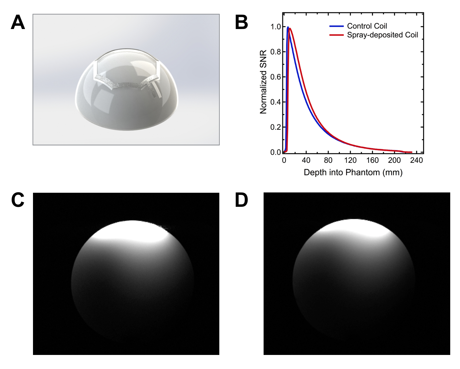
We found the optimum thickness of a sprayed conductor layer, by evaluating the effect of silver trace thickness on the value of Q unloaded. Fig. 2C shows performance of coils with different thickness of conductor, for two grades of Novacentrix silver inks – PSPI 1000 and PSPI 0250.Q unloaded increases to the maximum value of ~120 for PSPI-0250 and ~110 for PSPI-1000, when thickness of conductor is increased to ~40 um and ~50 um respectively. Increasing thickness beyond indicated values does not contribute to further increase in Q unloaded. Controlling capacitance allows to effectively tune the coil to the Larmor frequencies of MRI systems. Fig. 2D shows that varying area of a capacitor from 0.25 cm2 to 2 cm2 results in capacitance values ranging from 13 pF to 102 pF, which is sufficient to reach specific frequencies of 64 MHz (1.5 T) and 127 MHz (3.0 T) used in MRI systems (1,5). We fabricated fully functional coil deposited onto the 3D spherical substrate (Fig. 3A) and compared its performance to the control coil of the same geometry, consisting from metal copper traces with porcelain capacitors mounted onto 2D flexible substrate. Fig. 3B compares SNR of the two coils, evaluated using spherical phantom. Fig. 3C and 3D show axial slice of the phantom obtained with spray-deposited and conventional coils respectively. Due to improved conformability to the phantom, the spray-deposited coil has greater coverage throughout and similar SNR, despite of the lower performance characteristics of solution-processed materials. This illustrates advantage of using custom printed MRI receive coils to image areas of the body with complex curvilinear geometries, like patient’s neck. Furthermore, custom coils are constricting, which eliminates motion artifacts. Future work includes fabricating coil arrays and demonstrating imaging of the body parts relevant for clinical applications.Conclusion
We developed process for fabricating custom MRI receive coils using scalable additive manufacturing approach. Custom coils will enhance high quality clinical imaging by ensuring optimum fit to the body parts with complex geometries, reproducible placing on the patient and eliminating motion artifacts.Acknowledgements
We would like to acknowledge GE healthcare for providing the funding for this project and Carbon3D for support with manufacturing custom substrates. We thank James Tropp for guidance with electrical testing of coils.References
[1]Corea J.R, Flynn A.M., Lechêne B., Scott G., Reed G.D., Shin P.J., Lustig M., and Arias A. C. Screen-printed flexible MRI receive coils. Nature Communications, 7 ( 2016)
[2]Roemer, P. B., Edelstein, W. A., Hayes, C. E., Souza, S. P. & Mueller, O. M. The NMR phased array. Magn. Reson. Med. 16, 192–225 (1990)
[3]Darrasse, L. & Ginefri, J. C. Perspectives with cryogenic RF probes in biomedical MRI. Biochimie 85, 915–937 (2003)
[4]Mispelter, J. l., Lupu, M. & Briguet, A. NMR Probeheads for Biophysical and Biomedical Experiments: Theoretical Principles & Practical Guidelines (Imperial College Press, Distributed by World Scientific, 2006)
[5]Corea J.R., Lechene B.P.,Lustig M., and Arias A.C. Materials and Methods for Higher Performance Screen-Printed Flexible MRI Receive Coils, Magnetic Resonance in Medicine, 78, 2016
Figures