0019
Highly Flexible, Light Weight 24 Channel 3T Bilateral Brachial Plexus Array Worn as a Close Fitting Variable Size Vest1G. E. Healthcare Technologies, Aurora, OH, United States, 2G. E. Healthcare Technologies, Waukesha, WI, United States, 3Radiology, University of California, San Diego, La Jolla, CA, United States, 4Radiology, VA San Diego Healthcare System, San Diego, CA, United States, 5Electrical Engineering, University of California, San Diego, La Jolla, CA, United States
Synopsis
MR neurography of the Brachial Plexus (BP) is technically challenging, due in part to complex topographical anatomy that is sub-optimally accommodated with existing rigid receiver coil arrays. In this work we propose a wearable garment with integrated flexible loop receiver coils that conforms to the contour of the neck and shoulder, as well as variations in subject size. The loops can flex in multiple dimensions without seriously affecting noise correlation.
Introduction
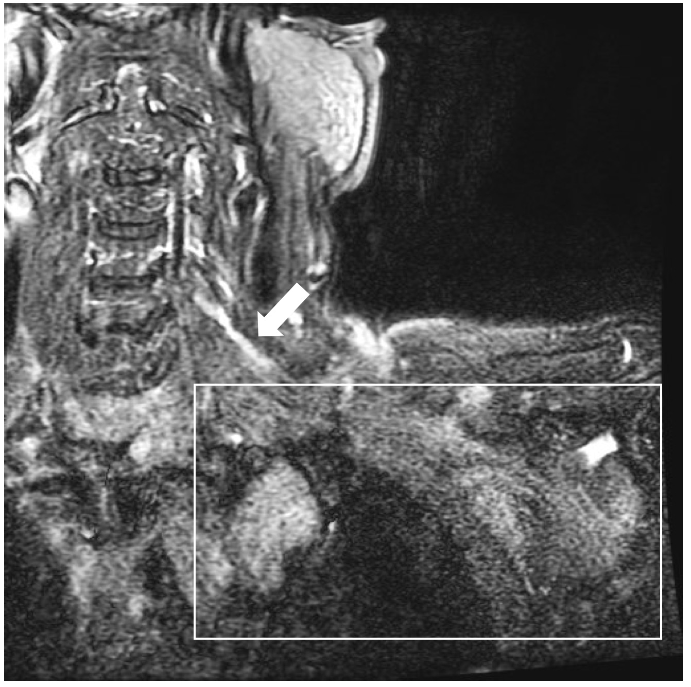
The BP is comprised of the ventral rami of C5 through C8 and the first thoracic nerve. BP (Figure 1) runs postero-laterally from the cervical spine with roots, trunks, divisions, cords and terminal nerves that traverse the soft tissues above and below the clavicle, and extend into the arm. This extended anatomic region requires a large field of coverage for complete evaluation. Historically MR imaging (commonly referred to as MR neurography or MRN) of BP has been done with rigid head/neck/spine (HNS) receiver arrays but such array elements are difficult to place close to the region of interest in a large percentage of patients with varying shape and size and consequently do not provide a satisfactory image quality (Figure 1). A new variable size and shape vest has been developed with air coil1,2 elements sewn directly onto the vest. The elements are light weight and flexible in all directions. Our purpose is to characterize this new highly flexible RF coil design to the needs for BP imaging.Methods
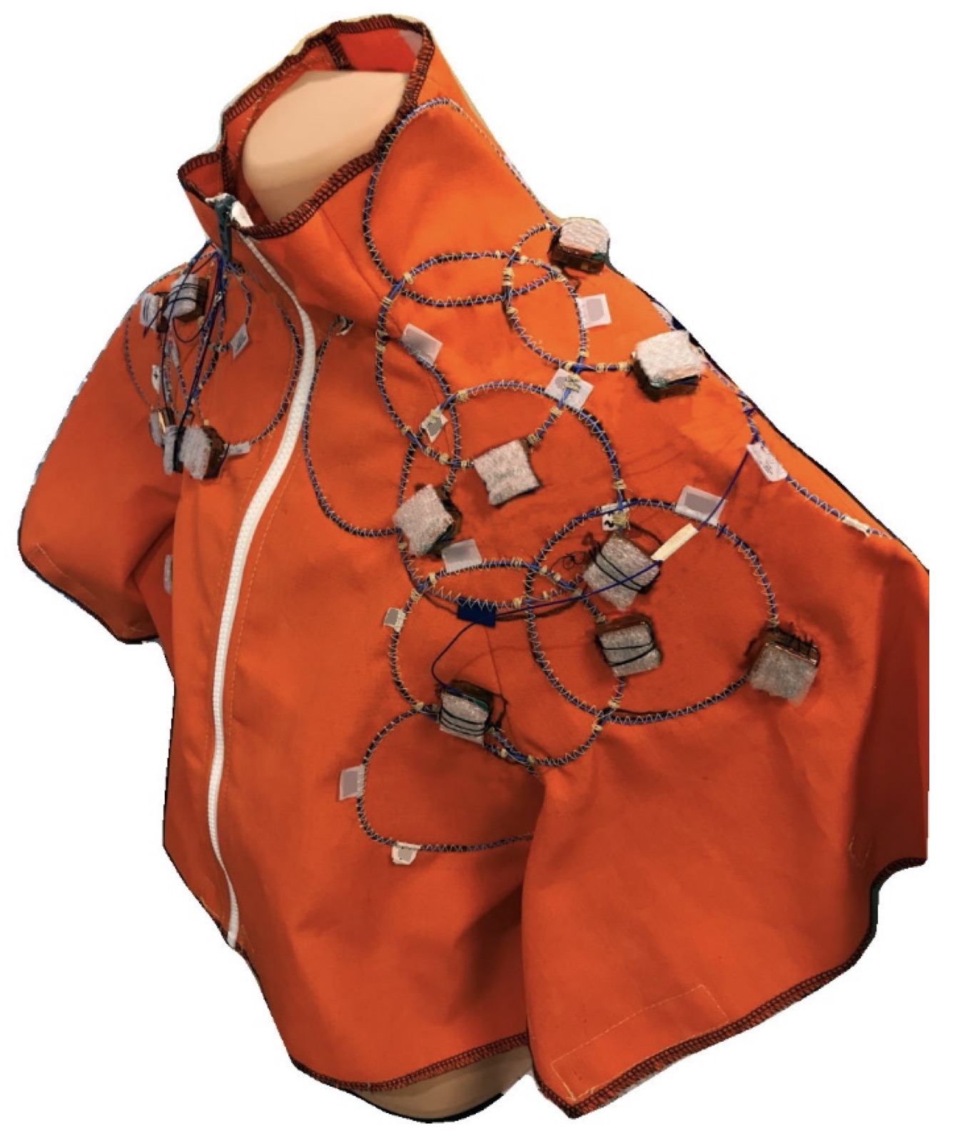
Coil Design: The BP was modeled based on several months of imaging. This model was then imported into a finite element full wave solver (HFSS, Ansys Inc) and merged with the average visible man model. In total twenty-four 11 cm diameter air coils loops were positioned manually (Figure 2) by a musculoskeletal radiologist familiar with BP anatomy. The air coil1,2 loops are made from highly flexible 1.0 mm wire optimized for zero reactance at 127.7 MHz. Loops were connected to a miniaturized (22 by 22 by 4.5mm) network containing baluns, transmit blocking, and a low impedance preamplifier. An output balun adds another 5 mm of build up height. Loops were sewn onto a vest made from TenCate Omniweave 600. This vest has a front plastic zipper and Velcro under the arms and laterally on the left and right side, allowing for close fit on patients of different size and shape. The posterior part of the coil has foam padding to protect the circuits from being damaged by the weight of the patient. Total weight of the vest with all loops, cables, padding and cable baluns is less than 0.5 kg. Decoupling during reception was achieved using the Roemer’s method3, as well as electric field containment and reduction methods. Coil-to-coil overlap can vary between underlapped and 35% overlapped with minor impact on noise correlation. The empty and loaded Q of the loops were measured on a network analyzer.
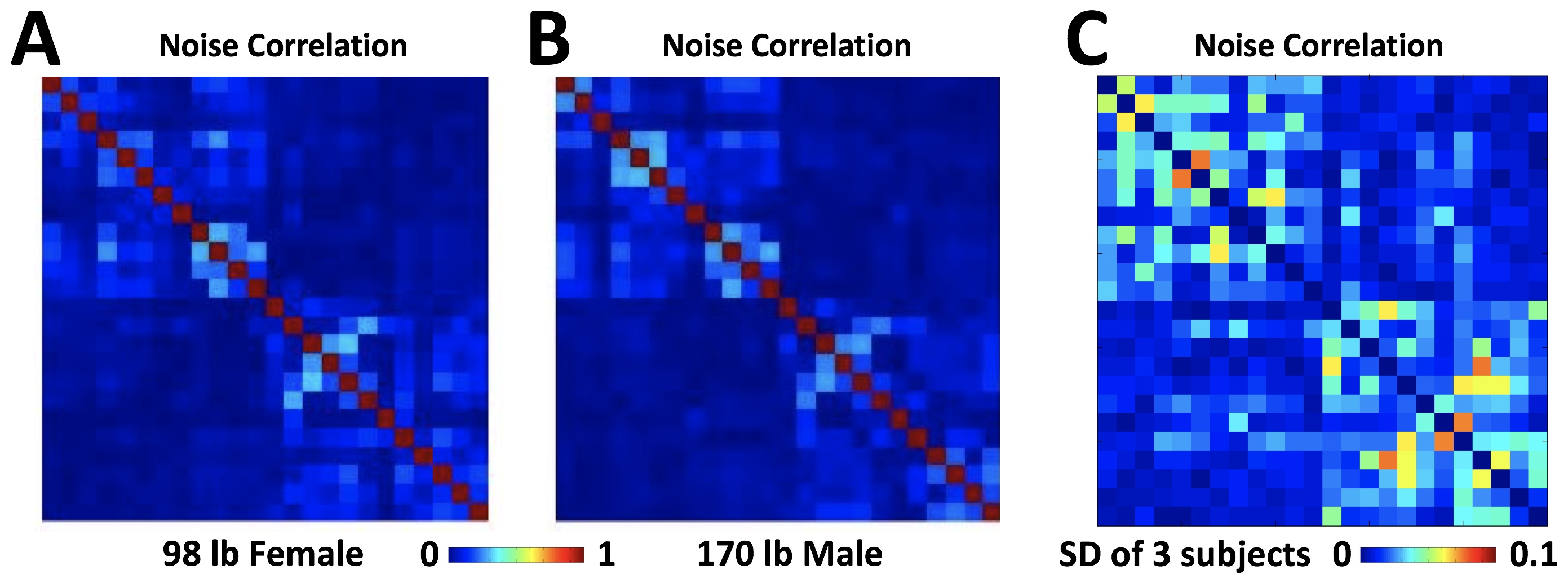
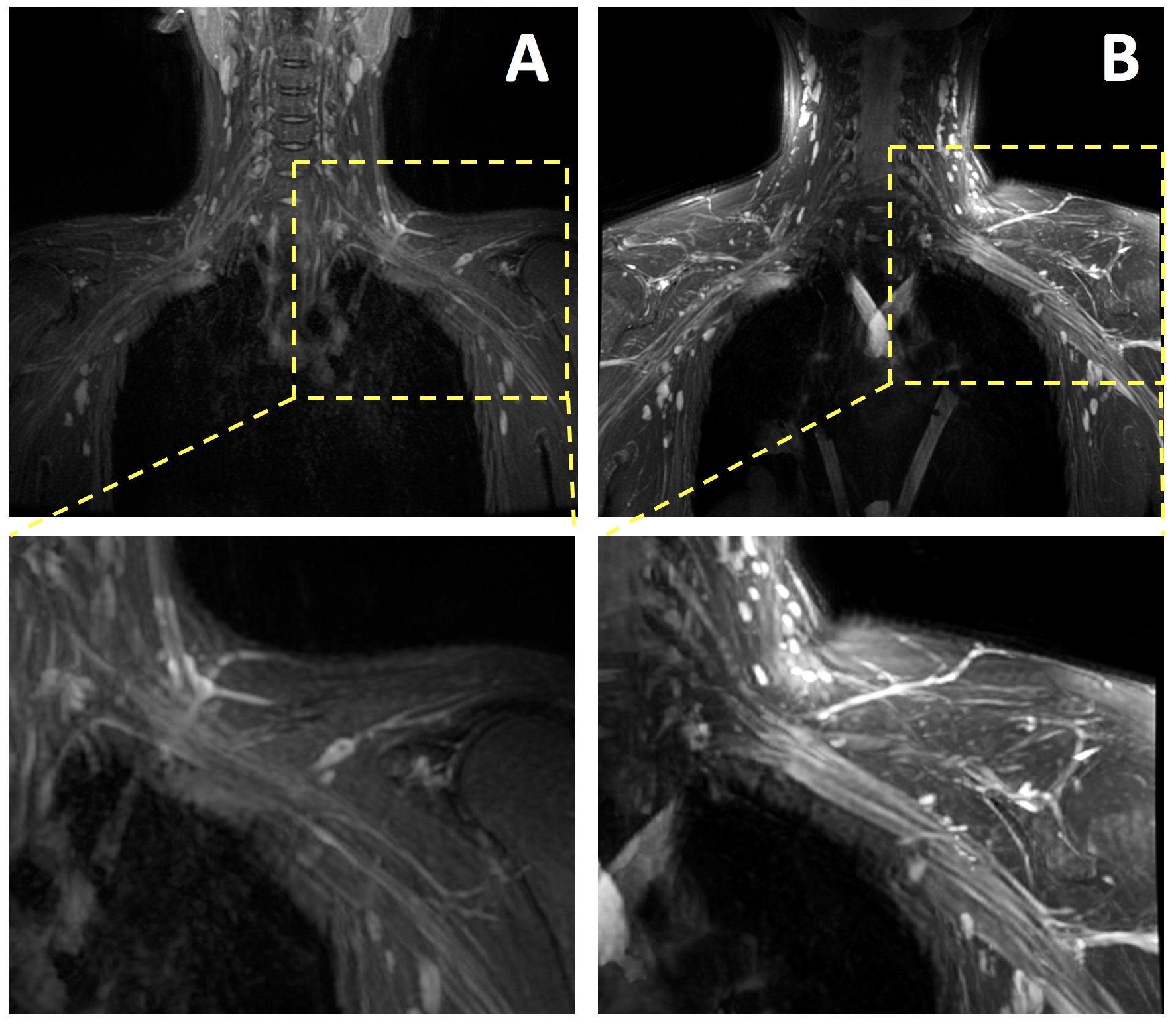
Coil Characterization in Volunteers: Three volunteers with varying weights (98 lb female, 145 lb male, 170 lb male) and shapes were imaged. On each volunteer, coronal spin echo imaging (TR=400 ms, TE=10 ms, ETL 4, FOV=30 cm, matrix=320x256, slice=4 mm) with and without RF was performed to calculate noise correlation3,4 (Figure 3) were 0 mean no correlation and 1 means perfect correlation. In addition, clinical images (coronal T2 IDEAL water: TR=3100 ms, TE=82 ms, ETL=14, FOV=34 cm, matrix=320x224, slice=4 mm, 23 slices; maximum intensity projection through 8 mm thickness) were obtained from a volunteer using both conventional Head-Neck-Spine/HNS (Figure 4A) and our BP coil (Figure 4B).
Results
The Q of the air coil elements was measured to be 125 empty and 40 loaded. The noise correlation matrices of the different size volunteers (Figure 3A, small; Figure 3B, large) were similar between volunteers (mean standard deviation of 0.02; Figure 3C), and did not show any appreciable coupling between elements evident by low correlation values (mean off- diagonal value of 0.007). Comparison of images from HNS (Figure 4A) vs. BP (Figure 4B) coils showed a marked qualitative improvement in signal-to-noise ratio, contrast and resolution of the nerve bundles with the use of BP coil. For RL acceleration g factors are <2 up to R=5 for 98lbs and up to R=4 for 140 and 170 lbs volunteers.Discussion
Presently the ongoing work is to optimize the placement, number and size of air coil elements to obtain optimal coverage and accelerated and non-accelerated SNR, using the finite element model of the BP inside body model. Work also remains to quantitatively determine performance improvements vs. conventional coils, in terms of SNR and CNR in vivo, as well as diagnostics in injury patients.Conclusion
A dedicated coil for BP application has been created and its noise characteristics has been described in volunteers of varying sizes. Image quality, when compared to that from a conventional HNS coil, showed marked improvements.Acknowledgements
Valuable support was received from Anthony Stafford at GE Coils Aurora and Liang Xuan at GE Healthcare WaukeshaReferences
1. P. Rossman et al., Characterization of a new ultra flexible low profile RF receive coil technology, Proceedings ISMRM 2017, 763.
2. S. Vasanawala et al., Development and Clinical implementation of very light weight and highly flexible Air technology arrays, Proceedings ISMRM 2017, 755.
3. P. Roemer et al., The NMR phased array, MRM 1990 Nov;16(2):192-225
4. V. Taracila et al., Proceedings ISMRM 2015, 4893.
Figures