0018
High Impedance Detector Arrays for Magnetic Resonance1Bernard and Irene Schwartz Center for Biomedical Imaging, New York University School of Medicine, New York, NY, United States, 2Center for Advanced Imaging Innovation and Research (CAI2R), New York University School of Medicine, New York, NY, United States, 3The Sackler Institute of Graduate Biomedical Sciences, New York University School of Medicine, New York, NY, United States
Synopsis
Resonant inductive coupling is commonly seen as an undesired fundamental phenomenon emergent in densely packed resonant structures, such as nuclear magnetic resonance phased array detectors. The need to mitigate coupling imposes rigid constraints on the detector design, impeding performance and limiting the scope of magnetic resonance experiments. Here we introduce a high impedance detector design, which can cloak itself from electrodynamic interactions with neighboring elements. We verify experimentally that the high impedance detectors do not suffer from signal-to-noise degradation mechanisms observed with traditional low impedance elements. Using this new-found robustness, we demonstrate an adaptive wearable detector array for magnetic resonance imaging of the hand. The unique properties of the detector glove reveal new pathways to study the biomechanics of soft tissues, and exemplify the enabling potential of high-impedance detectors for a wide range of demanding applications that are not well suited to traditional coil designs.
Introduction Resonant inductive coupling is commonly seen as an undesired fundamental phenomenon emergent in MR phased array detectors. The need to mitigate coupling imposes rigid constraints on the detector design, impeding performance and limiting the scope of magnetic resonance experiments. Here we introduce a high impedance detector design (HIC), which can cloak itself from electrodynamic interactions with neighboring elements. To illustrate the unique degrees of freedom provided by HIC elements, we created a wearable coil in the form of a glove. The unique properties of the detector glove reveal new pathways to study the biomechanics of soft tissues, and exemplify the enabling potential of high-impedance detectors for a wide range of demanding applications that are not well suited to traditional coil designs.
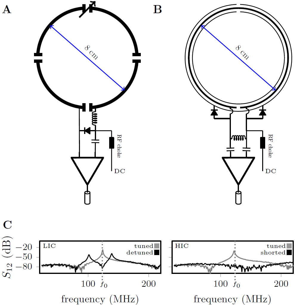
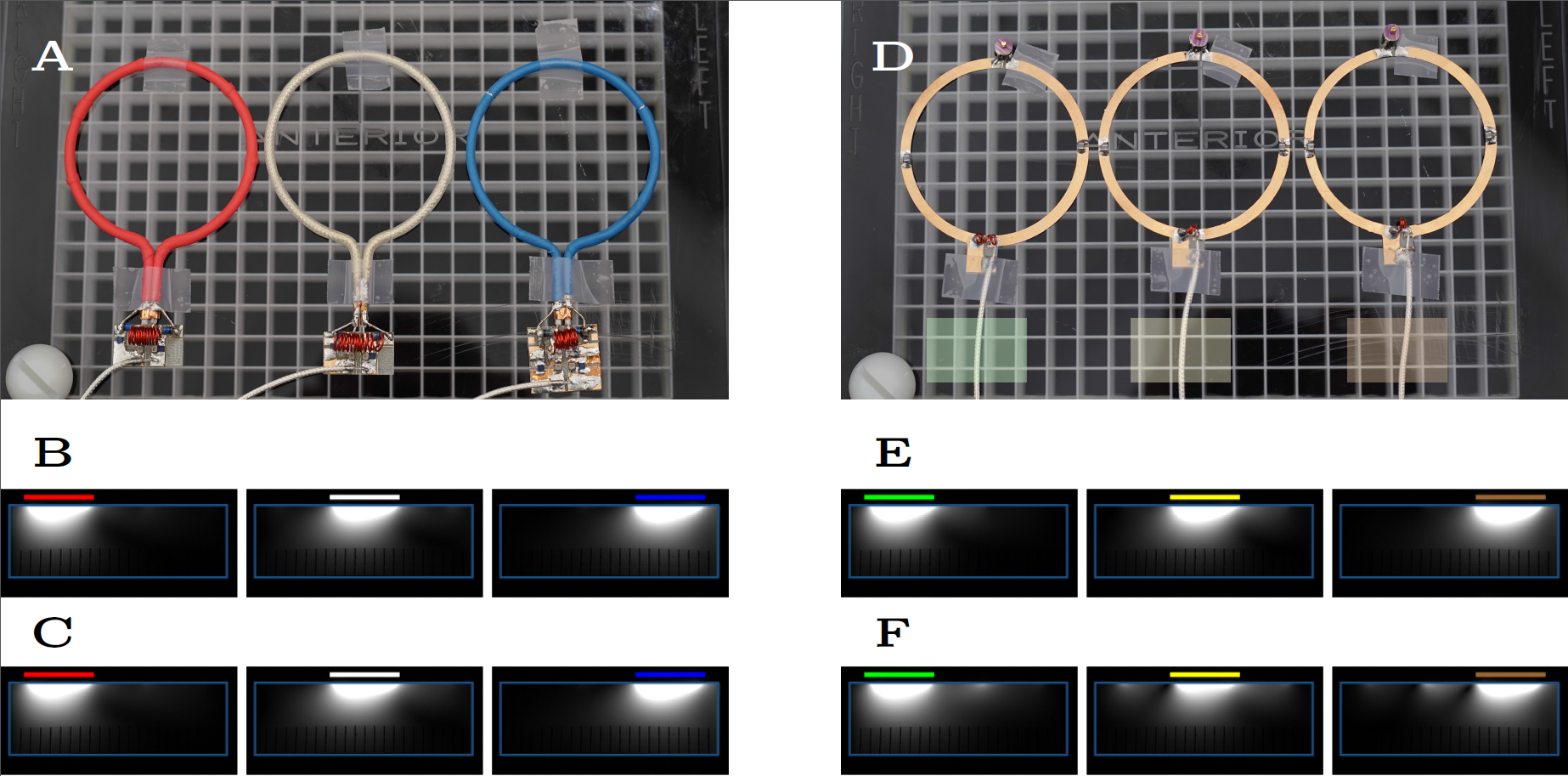
Method Inspired by developments in wireless power transfer systems [1, 2], we designed a high impedance resonant coaxial NMR probe (Fig. 1B). In contrast to conventional LIC elements, there are no lumped capacitors to adjust the resonance frequency or distribute the current. Instead, our HICs were tuned by adjusting the length, the relative permittivity of the substrate, and the ratio between inner and outer conductor diameter [3], such that the Larmor frequency of interest coincides with the lowest resonance of the structure. Figure 1A and 1B show schematic drawings of a traditional low impedance coil (LIC) [4] and the proposed HIC. Two PIN diodes were used to detune the HIC during transmission; a “reverse preamplifier decoupling” scheme, which creates low impedance at the port, suppresses all currents in the HIC arrangement during reception. A 3D printer (Fortus 360mc, Stratasys, Minnesota) was used to explore the design space of possible coaxial substrate configurations. To maximize flexibility of the design, we used a 0.7 mm separation between the inner and outer conductor, leading to a coil diameter of 80 mm when tuned to 123 MHz. To evaluate how well HICs cloak themselves from one another, we placed three identical HIC elements (Figure 2A) side by side on top of a large conductive phantom (er=77, σ=0.53S/m). Three conventional 8-cm-diameter LICs (Figure 2B) were constructed for comparison. GRE images were obtained for SNR analysis. Eight HIC elements were stitched onto a cotton glove, tracing the contours of each finger with an individual coil to allow all the joints in each finger to articulate freely (Figure 4). Two additional elements were stitched on the top of the hand and wrist, and one more on the bottom, allowing the carpal bones in the wrist joint to be studied as well.
Work bench results: Figure 1C shows the resonances observed with a double pickup probe experiment when the coil is tuned and detuned.
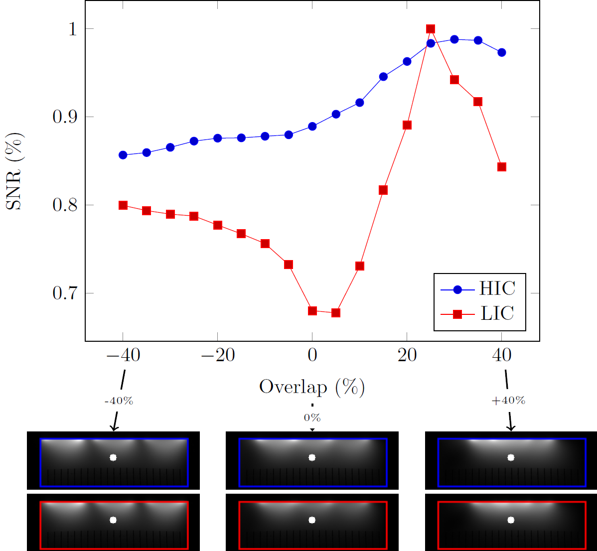
Phantom results: Unlike the LIC measurements (Figure. 2 E vs F), the HIC elements show no evidence of signal coupling between the elements (Figure. 2C vs D). Although distinct coil-profiles are a key feature of the NMR phased array, crucial for parallel imaging [5, 6, 7] and modern multi-band techniques [8, 9], decoupling should not come at the expense of a reduced signal to noise ratio (SNR). To investigate this aspect, we evaluated the SNR at 4.2 cm (≈1/2 the coil diameter) depth below the center element as a function of coil overlap (Fig. 3). LIC elements reach their optimal performance when critically overlapped (≈25% overlap). When the outer coil elements are moved further apart or closer together, the SNR quickly deteriorates. The HIC elements, on the other hand, show almost no degradation in SNR as the overlap between them is changed.
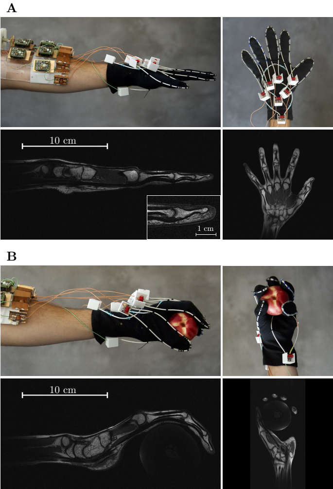
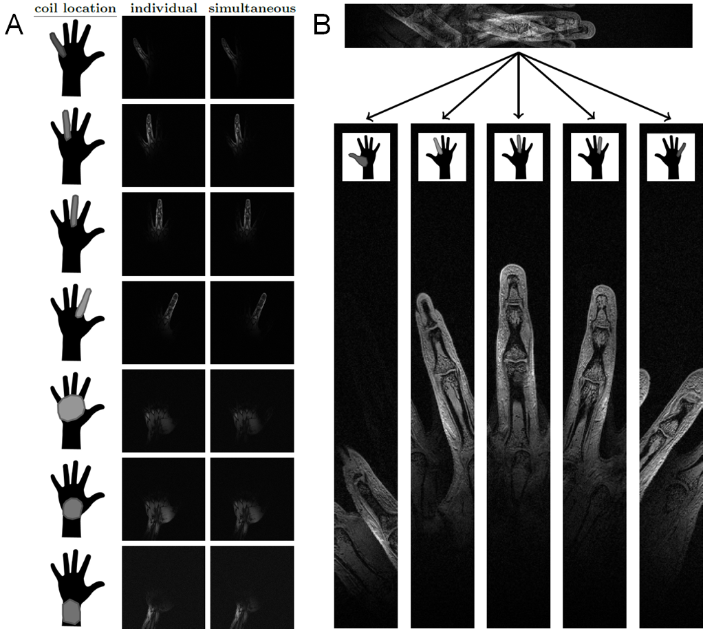
In-vivo results with the HIC glove coil: Figure 4A shows photos of the glove coil with the hand starched out and the corresponding T1 weighted MR images. The close-fitting elements enable fast imaging with exquisite detail (250µm, 2mm slice, TA=2min 30sec). Figure 4B shows the same hand in a different position, now holding a peach, to illustrate how the HIC elements conform to the shape of the hand, and the corresponding T1 weighted MR images. Figure 5A shows GRE images acquired in 8 separate measurements, each with only one coil activated at a time (center column). Gradient recalled echo images acquired in one single measurement with all coils activated at the same time (right column). Although the coil elements on each finger are directly adjacent to one another in this configuration, distinct coil profiles are maintained (Figure 5B).
Conclusion: The proposed HIC elements pave the way towards size adjustable and flexible MR coils that allow greater patient comfort and facilitate new areas of research.
Acknowledgements
This work was performed under the rubric of the Center for Advanced Imaging Innovation and Research (CAI2R, www.cai2r.net), a NIBIB Biomedical Technology Resource Center (NIH P41 EB017183). We thank Ryan Bown and Markus Vester for the many valuable discussions, and Zidan Yu for her help during the experiments.References
[1] Kurs A., et al., Wireless Power Transfer via Strongly Coupled Magnetic Resonances. Science, 2007;317:83-86.
[2] Tierney B., Grbic A., Planar shielded-loop resonators for wireless non-radiative power transfer. IEEE Antennas and Propagation Society International Symposium (APSURSI). 2014; DOI:10.1109/APS.2013.6711080.
[3] Zhang, B., Sodickson D.K. and Cloos M.A., High impedance detector arrays for magnetic resonance. https://arxiv.org/abs/1709.03416.
[4] Roemer P.B., et al., The NMR Phased Array. Magn. Reson. Med., 1990;16:192-225.
[5] Sodickson D.K., Manning W.J. Simultaneous acquisition of spatial harmonics (SMASH): fast imaging with radiofrequency coil arrays. Magn. Reson. Med., 1997;38:591-603.
[6] Pruessmann K., Weiger M, Scheidegger MB, Boesiger P. SENSE: sensitivity encoding for fast MRI. Magn. Reson. Med., 1999;42:952-962.
[7] Griswold M., et al., Generalized autocalibrating partially parallel acquisitions (GRAPPA). Magn. Reson. Med., 2002;47:1202-1210.
[8] Larkman D.J., Hajnal J.V., Herlihy A.H., Coutts G.A., Young I.R., Ehnholm G. Use of multicoil arrays for separation of signal from multiple slices simultaneously excited. J Magn. Reson. Imaging. 2001;13(2):313-317.
[9] Setsompop K., et al., Blipped-controlled aliasing in parallel imaging for simultaneous multislice echo planar imaging with reduced g-factor penalty. Magn. Reson. Med., 2012;67:1210-1224.
Figures