0017
Towards wearable MR detection: A stretchable wrist array with on-body digitization1Institute for Biomedical Engineering, University and ETH Zurich, Zurich, Switzerland, 2Electronics Laboratory, ETH Zurich, Zurich, Switzerland, 3Integrated Systems Laboratory, ETH Zurich, Zurich, Switzerland
Synopsis
Today, MRI coils can be made flexible and stretchable. Signals can be sent out of bore by optical or wireless links. Nonetheless, wearable digital coil arrays have not yet found their way into MRI although enhanced patient comfort and workflow can be expected. In this work we explore the feasability of stretchable coil arrays with on-coil digitization and optical transmission, and present a first implementation for wrist imaging.
Introduction
Today, MRI coils can be made flexible1 and stretchable2. Signals can be sent out of the bore by optical3 or wireless links4. Even on-coil digitization in the harsh electromagnetic environment has been rendered feasible through integrated circuits (IC)5. Nonetheless, wearable digital coil arrays have not yet found their way into MRI although enhanced patient comfort and workflow can be expected. Combining these latest advancements into an actual wearable multichannel array presents itself as a non-trivial task. For wearability, size, weight and power restrictions of the electronics apply. A wearable array has to consider the great anatomical diversity of patients - tuning and matching have to be robust to changes in coil size. Further, when scaling the number of coils, the intricate interactions among coils and receivers have to be controlled - classical parameters for array design such as geometric decoupling are difficult to achieve with changing geometry. In this work we explore the feasibility of stretchable coil arrays with on-coil digitization and optical transmission, and present a first implementation for wrist imaging.Methods
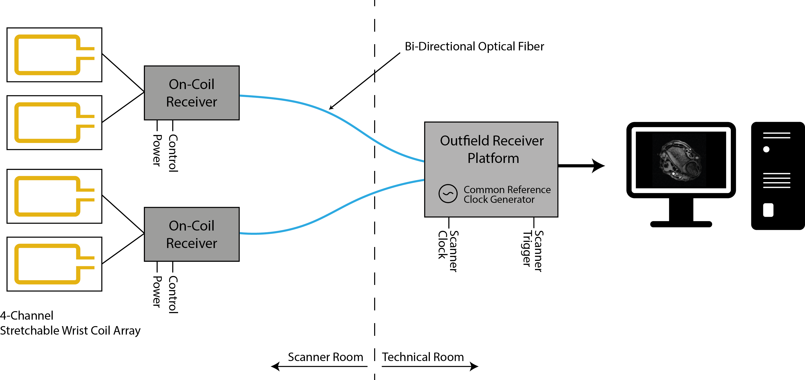
Our system consists of a 4-channel wearable wrist array with on-coil signal digitization. The digitized data is sent via an optical link to an outfield receiver platform where signals of multiple on-coil receivers are collected, processed and image formation is performed6 (Fig. 1).
Coil Array
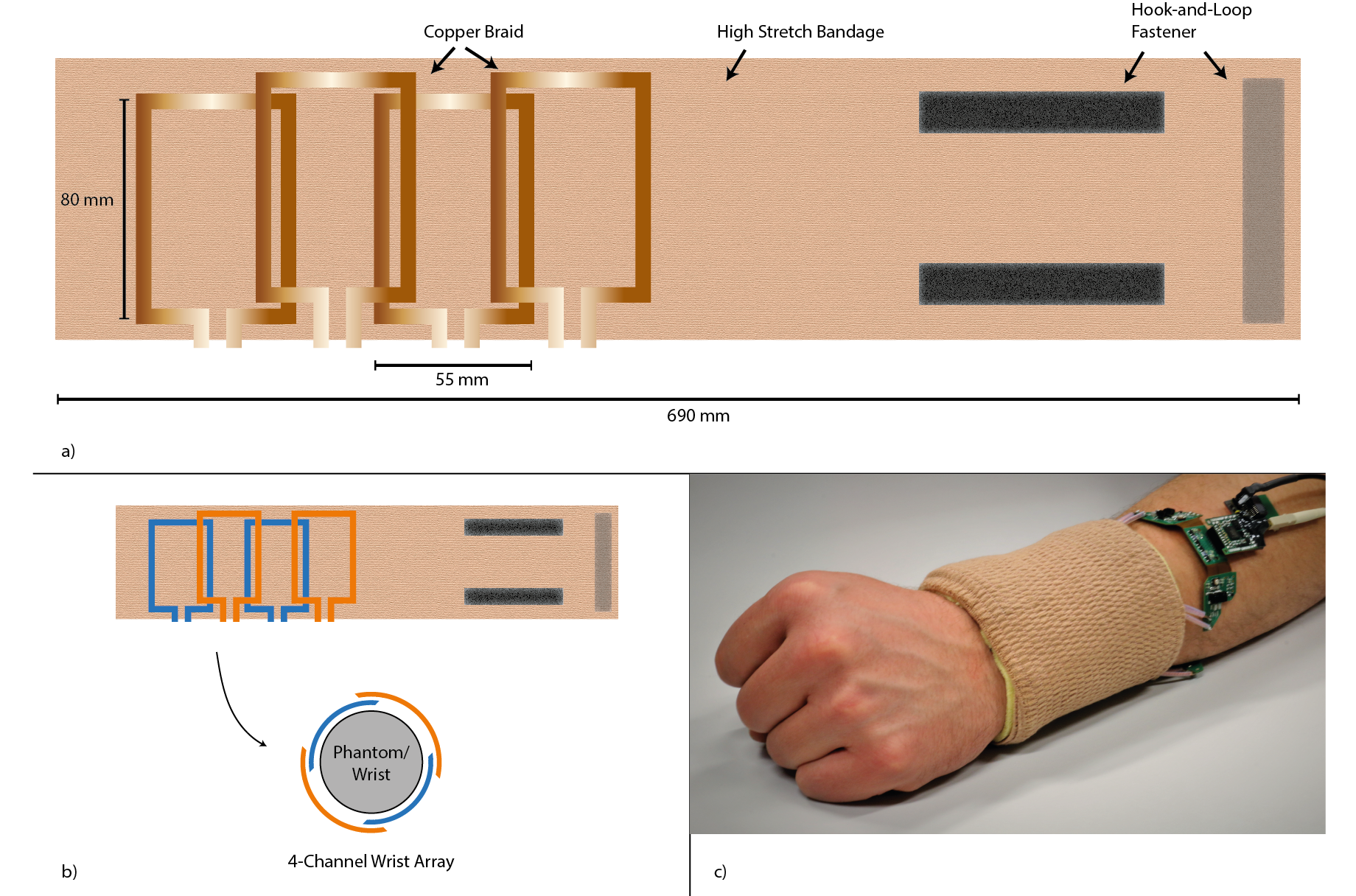
A 4-channel elastic coil array for wrist imaging was designed2 (Fig. 2). A high-stretch bandage (IVF Hartmann AG, Switzerland) was used as the flexible and stretchable base material. A 5-mm copper braid (Easy Braid, USA) was chosen as coil conductor and sewn onto a 690 mm piece of the bandage to form four coils. Each of these is of size 55x80mm in the relaxed state (Fig. 2a) extending to 80x80 when fully stretched. The location of coils on the flexible substrate and the dimensions of the same is selected to achieve geometric decoupling7 (Fig. 2b). In its stretched state, closely fitting a phantom or a volunteer’s wrist (Fig. 2c), each individual coil was tuned to 127.7 MHz and matched for use in a 3T MRI system.
Coil Interface with Receiver IC
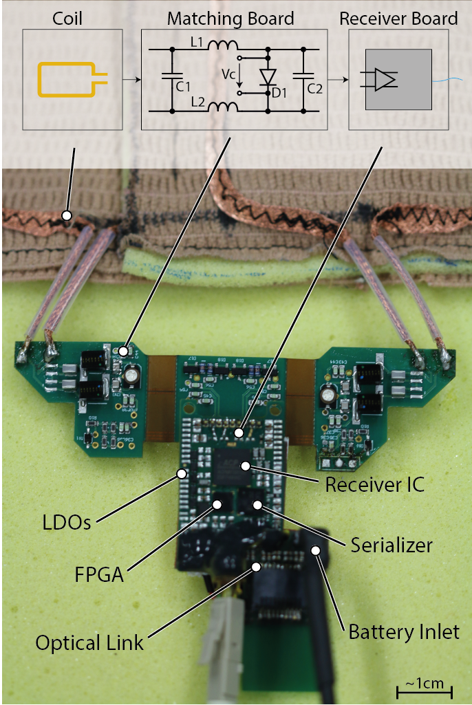
A rigid-flex printed circuit board (PCB) interfaces each coil to the fully differential preamplifier of the receiver IC5 through a pi matching network embodying non-magnetic, high RF power, low ESR capacitors (American Technical Ceramics, USA) and high Q inductors (Coilcraft, USA) (Fig. 3). The pi matching network functions as a 90°- phase shifter for preamplifier decoupling7. Detuning is implemented through non-magnetic PIN diodes (MACOM, USA). Parallel digital output of the receiver IC is encoded on a FPGA (Lattice, USA) and serialized (Texas Instruments, USA) before being transmitted via a bi-directional optical link. The on-coil circuitry is powered by Lithium-Ion batteries. PCB layout and geometry was optimized for in-bore operation using finite element modeling (FEM).
Receiver Synchronization
Synchronization of multiple receivers is accomplished by locking the on-chip local phase locked loop (PLL) circuitry to an optically fed common external reference clock. The RF excitation phases, which are governed by the proprietary console were extracted by recording the excitation pulse during the coil detune state and using it’s unwrapped phase information8,9.
Imaging Experiments
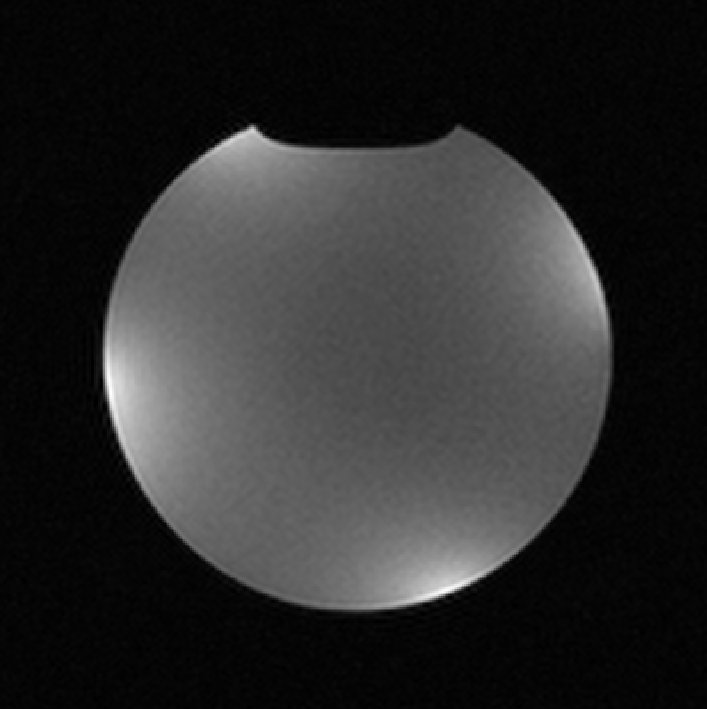
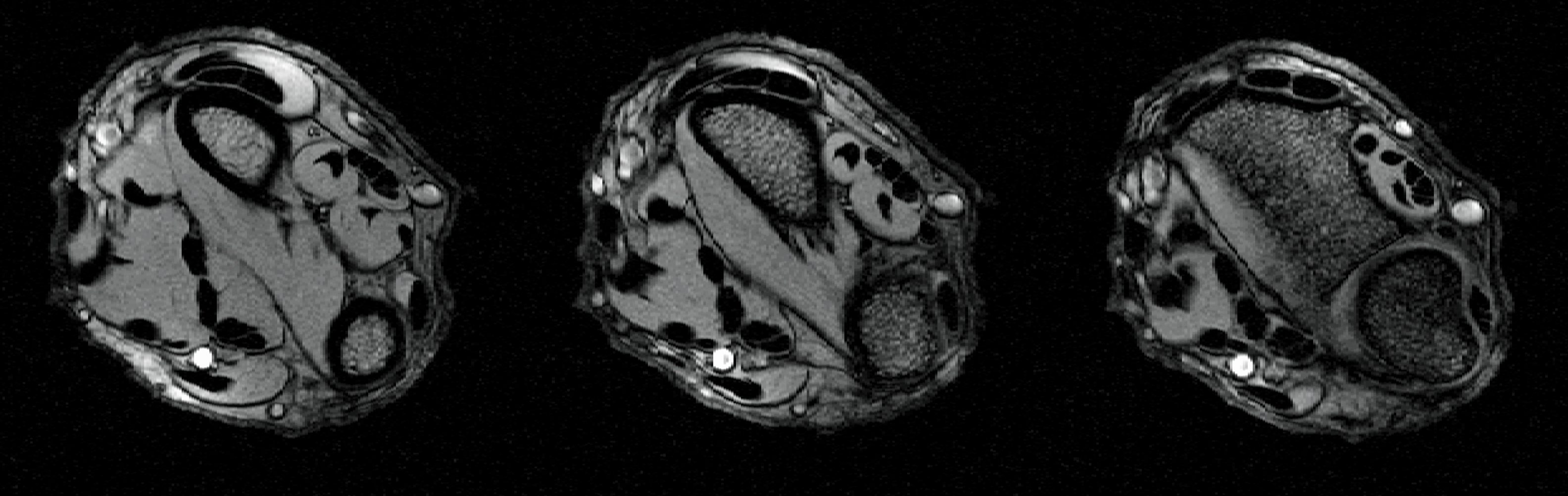
A phantom image (Fig. 4) was acquired on a Philips 3T Ingenia system (Philips, Netherlands) using a standard gradient echo sequence (FFE) (TR= 230ms, TE= 8ms, flip angle = 70°, NSA = 5, Voxel Size = 0.45 x 0.45 x 5 mm3 ). The phantom fluid was CuSO4 doped water saline water to emulate human tissue. FFE in-vivo images (TR= 132ms, TE= 8.3ms, flip angle= 30°, NSA= 4, Voxel Size = 0.25 x 0.25 x 5 mm3) of a healthy volunteer’s wrist was acquired (Fig. 5).
Results
Tuned to 127.7 MHz the coils provided a Qunloaded/Qloaded = 85/24 = 3.5. Stretching by 18% shifted the center frequency by 3.2 MHz which was compensated on a per subject basis. The in-vivo images of a human wrist show good coverage and image uniformity (Fig. 5). The power consumption per channel is 1.05 W with most power currently consumed by the serializer and optical module.Discussion
A wearable and stretchable 4-channel coil array with fully integrated on-coil digital receivers is presented. Such arrays promise to avoid cabling and an increase in patient comfort. Furthermore, real-time scanning of joints in motion is enabled2. The performance of the coil could be improved by adaptive matching of the preamplifier10 to compensate for the variable load presented by the coils.Acknowledgements
This research was founded by the Nano-Tera.ch initiative.References
1. J. R. Corea et al., “Screen-printed flexible MRI receive coils,” Nat. Commun., vol. 7, p. 10839, 2016.
2. J. A. Nordmeyer-Massner, N. De Zanche, and K. P. Pruessmann, “Stretchable coil arrays: Application to knee imaging under varying flexion angles,” Magn. Reson. Med., vol. 67, no. 3, pp. 872–879, 2012.
3. J. Reber et al., “In-Bore Broadband Array Receivers with Optical Transmission,” Proc. Int. Soc. Magn. Reson. Med., vol. 22, p. 619, 2014.
4. K. Aggarwal et al., “A Millimeter-Wave Digital Link for Wireless MRI,” IEEE Trans. Med. Imaging, 2016.
5. B. Sporrer et al., “A sub-1dB NF dual-channel on-coil CMOS receiver for Magnetic Resonance Imaging,” Dig. Tech. Pap. - IEEE Int. Solid-State Circuits Conf., vol. 60, pp. 454–455, 2017.
6. J. Marjanovic, J. Reber, D. O. Brunner, and K. P. Pruessmann, “An FPGA Based Real-Time Data Processing Structure - Application to Real-Time Array Coil Data Compression,” in Proc. Intl. Soc. Mag. Reson. Med, Singapore, 2016, vol. 24, p. 1786.
7. P. B. Roemer, W. A. Edelstein, C. E. Hayes, S. P. Souza, and O. M. Mueller, “The NMR phased array,” Magn. Reson. Med., vol. 16, no. 2, pp. 192–225, 1990.
8. J. Reber, J. Marjanovic, C. Schildknecht, D. O. Brunner, and K. P. Pruessmann, “Correction of Gradient Induced Clock Phase Modulation for In-Bore Sampling Receivers,” Proc. Intl. Soc. Mag. Reson. Med, Honolulu, USA, vol. 25, p. 1056, 2017.
9. G. Scott, F. Robb, J. Pauly, and P. Stang, “Software Synchronization of Independent Receivers by Transmit Phase Tracking : eg . an N = 256 sample , T = 4 . 1 ms tone of A / σ = 100 , can estimate to 60 mHz even though the DFT bin is 244 Hz .,” Proc. Intl. Soc. Mag. Reson. Med, Honolulu, USA, pp. 4–6, 2017.
10. M. Pavan, “Adaptive detector matching for SNR optimization in MRI,” 2015.
Figures