Demystifying Dielectrics
1NYU Langone Medical Center
Synopsis
Historical and recent examples of materials having a high relative electric permittivity as used to enhance or even create the electomagnetic fields in MRI for improved performance will be reviewed with an eye to the physical mechanisms by which they can act to improve MRI performance.
Syllabus
In MRI, radiofrequency (RF) magnetic fields are used to excite nuclei to a state where they can produce a detectable RF signal. Traditionally both the production of the excitation fields and the reception of signal rely on use of RF coils consisting of discrete metallic conductors following specific paths through space, interrupted occasionally by capacitors, inductors, and other electronic components as needed to accomplish tuning, matching, decoupling from other coils, and (in the case of receive-only coils and arrays) detuning during RF excitation.
More recently, and coincident with the use of MRI with high static field strengths and RF field frequencies where RF fields are clearly perturbed by human tissues, dielectric materials have been used increasingly to either improve the distribution of the RF fields produced by traditional coils in excitation (1-6), improve efficiency of traditional coils in excitation or reception (thus reducing SAR in transmission and improving SNR in reception) (5-8), or even to replace the RF coils all together (9, 10). A more thorough review of dielectric materials and applications in MRI was published a few years ago (10). Here we will focus on explaining the mechanisms by which passive dielectric materials can be used to improve performance of traditional coils.
The term “dielectric” in some situations is used to refer to a material that is a good electrical insulator and a poor electrical conductor, but in the applications of interest here we are more specifically interested in materials having a high electric permittvity. In the following the term HPM is thus used to indicate a High-Permittivity Material.
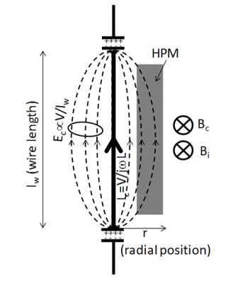
Every traditional RF coil is associated with significant electric fields throughout space resulting from the voltages required to drive electrical currents in the coil. In principle, according to Maxwell’s modified Ampere’s Law (Equation 1) where B1 is the desired RF magnetic field, Ic=σE is the conduction current found primarily in the conductive elements of the coil (producing Bc in Fig. 1), and jωεrε0E is the “displacement current” resulting from the electric fields throughout space (producing Bi in Fig. 1). Conventional current design considers only the conduction current in the coil conductors, but with strategic use of HPMs (having εr>>1 where εr,air=1), the electric fields throughout space can also be utilized to add to the B1 field in the region surrounded by the HPM and coil.
This utilization of the existing electric fields with HPMs to produce significant displacement currents results in both lower voltages and currents in the coil and lower Electric fields throughout space required to produce a given B1 field in the sample, and thus results in a more efficient and sensitive coil.
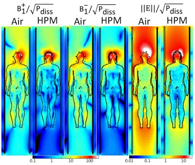
Because signal and noise have different origins in MRI, increasing the magnetic fields in the ROI relative to the electric fields throughout space can improve SNR. Sensitivity to signal is proportional to the strength of the RF magnetic field in the ROI, but sensitivity to noise is proportional to the strength of the RF electric fields throughout the entire subject.
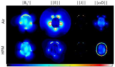
With strategic use of Numerical simulations illustrating this mechanism for a head array are presented in Fig.s 2 and 3. Using HPMs as we propose, to enhance the B1 field in the ROI while reducing electric fields everywhere, will increase both SNR and transmit efficiency (resulting in reduced SAR).
Additionally, the displacement currents in the HPM are much more distributed than the conduction currents in the traditional coils. This can allow for lower local SAR in transmission, as well as overall current distributions that better match the ideal current patterns for a given situation, which are always distributed through space more than traditional coils allow (11).
Finally, it is important to note that there is some work involved in determining what materials arranged in what configuration will result in improved performance. Either the wrong materials or the wrong configuration can also worsen performance. Ongoing efforts are focused on automated methods for selecting optimal materials and configurations (12), as well as to determine and implement configurations that will work well for a wide range of subjects (13).
Acknowledgements
No acknowledgement found.References
1. DC Alsop, et al., Magn Reson Med 1998;40:49-54
2. QX Yang, et al., J Magn Reson Imaging 2006;24:197-202
3. KM Franklin, et al., J Magn Reson Imaging 2008;27:1443-11447
4. JEM Snaar, et al., NMR Biomed 2011;24:873–887
5. WM Brink and AG Webb, Magn Reson Med 2014;71:1632-1640
6. WM Brink, et al., J Cardiovasc Magn Reson 2015;17:82
7. QX Yang, et al., Magn Reson Med 2011;65:358-362
8. CM Collins et al., Proc 23rd ISMRM 2014:404
9. H Wen et al., J Magn Reson B 1996;110(2):117-123
10. AG Webb, Concepts in Magnetic Resonance Part A 2011;38A(4):148-184
11. R Lattanzi and DK Sodickson, Magn Reson Med 2012;68(1):286-304
12. WM Brink and AG Webb, Proc ICEAA 2013:528-531
13. CM Collins and QX Yang, Proc 23rd ISMRM 2014:1340
Figures


Figure 2. Fields and currents on axial plane through the center of brain in a close-fitting transmit array without (top) and with (bottom) a 5mm thin layer of HPM between the coil and the head. Linear scale max is 3μT for |B1+|, 1000V/m for ||E||, 5000A/m2 for conduction current density ||J||, and 250A/m2 for displacement current density ||ωD||. Fields are normalized to 1µT average in brain on this plane. Results show that HPM (with distributed displacement currents) results in more homogeneous fields, smaller required conductive currents, driving voltages, and E field through space to achieve desired B1. Key numerical results are included in Table in Figure 4.


