Construction of Rx Arrays
1University of Glasgow, Glasgow, United Kingdom, 2Max Planck Institute for Biological Cybernetics, Tuebingen, Germany
Synopsis
We aim to present a step-by-step method to construct a transmit array. The measurements will be demonstrated using an 8-channel transmit array. We will then extend this method to the development of a dual-row transmit array. Construction and charecterisation of a receive coil element and combining a transmit and recieve array is also included.
Highlights
-
Step by step approach to the design of a
transmit and receive array
- How to characterize a receive coil element
- Combining transmit arrays and receive arrays
Target audience
RF engineers, researchers interested in ultra-high field MRI and parallel transmit.Outcome/Objectives
We aim to motivate and educate UHF researchers to develop customized coils for UHF applications.Introduction
In this presentation we focus on the design of RF coils for MRI of the human brain at UHF. Most commonly used RF coils for UHF applications are either transceiver arrays or transmit-only receive-only arrays (ToRo) because these designs offer the flexibility to tailor the RF field distribution (RF shimming). Transceiver arrays can be confined closer to the head while the transmit array in the ToRo design must be large enough to accommodate the receive array. Hence, transceiver arrays are well suited to maximize the transmit efficiency and ToRo designs offer maximum signal to noise ratio (SNR).Methods
We will present a step-by-step guide towards the construction of a ToRo array for imaging the human brain.
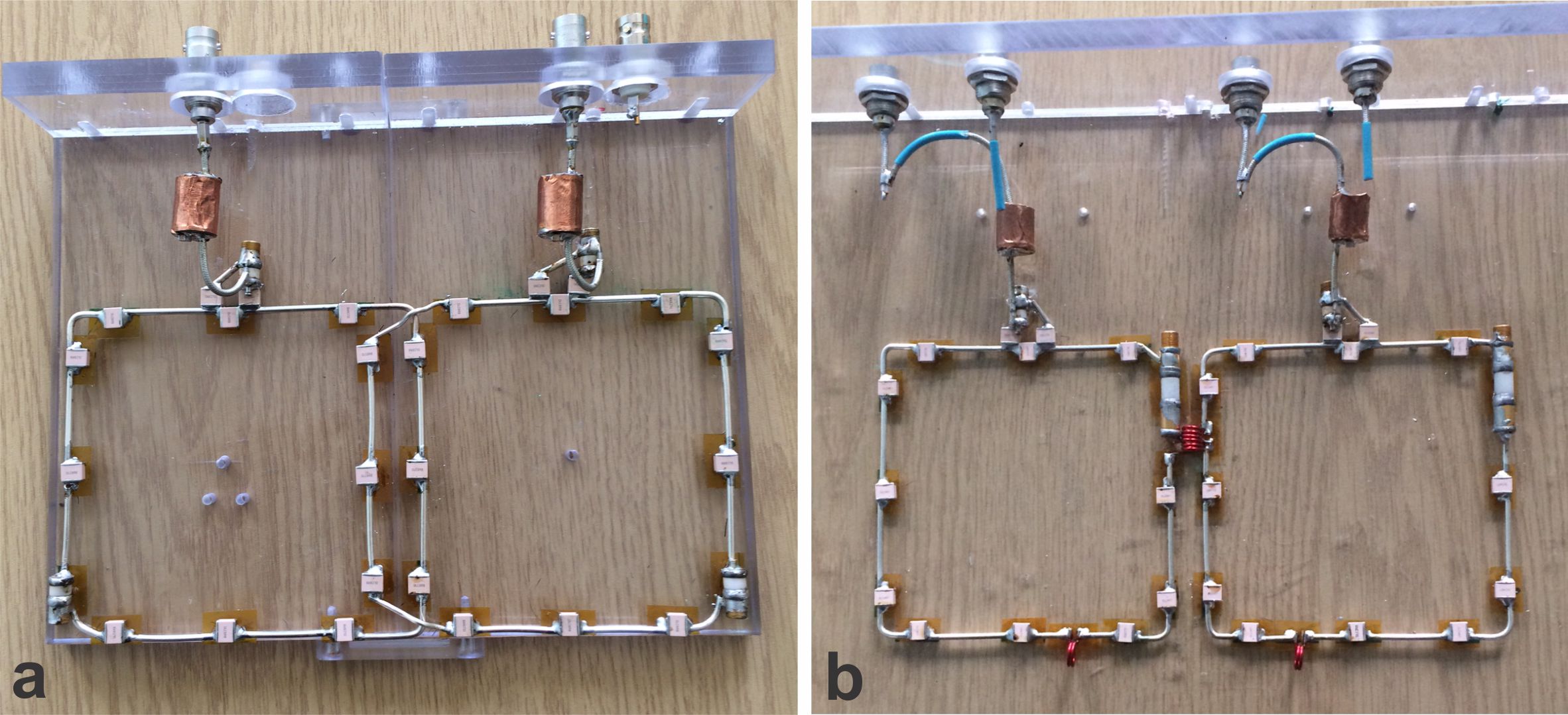
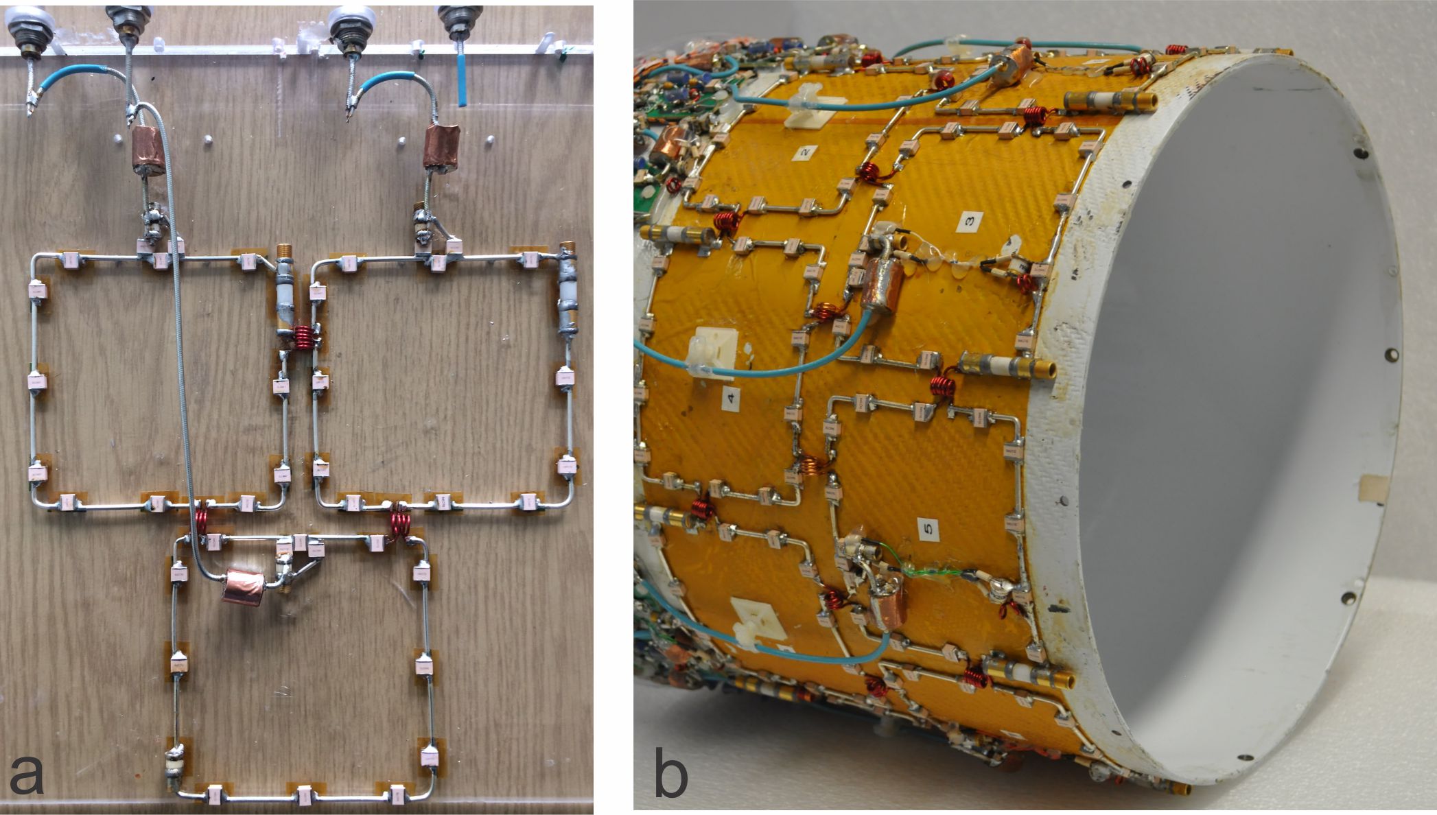
Transmit array: A single loop forms the fundamental building block of a transmit array. Constructing a single loop consists of distributing the capacitors in the loop, impedance matching to 50 ohms, building a cable trap and active detuning. A schematic of a single loop element and its implementation is shown in figure 1. In figure 2, two loops are placed next to each other and the coupling between the loops can be cancelled either by geometric overlap (Fig. 2a) or using inductors (Fig. 2b). This process is then extended around the cylinder to form an 8-channel transmit array (Fig 3).
It is beneficial to arrange the transmit elements in multiple rows to extend the excitation along the longitudinal direction. An example of such an implementation is shown in figure 4a. It is critical to route the cables feeding the lower row along the virtual ground of the upper row. This method can now be extended to form a dual-row transmit array (Figure 4b).
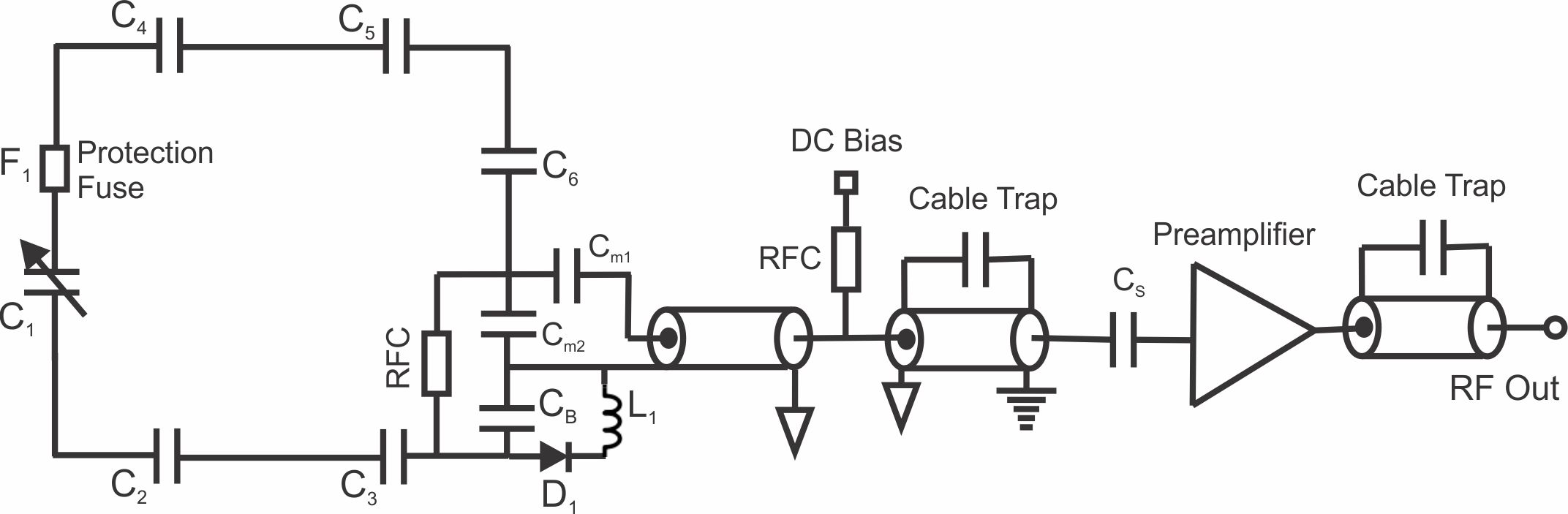
Receive array: An equivalent circuit of a single receive element is shown in figure 5. The capacitors CM1 and CM2 forms the matching network and CB together with L1 and D1 forms the blocking circuit. When PIN diode D1 is turned ON during transmit, CB and L1 are in parallel, creating a high impedance at the Larmor frequency. A protection fuse (F1) is added for secondary safety. The receive element is connected to a low input impedance preamplifier. Preamplifier decoupling is achieved by transforming the low impedance of the preamp to a high impedance across the coil input. We will demonstrate tuning, matching, active detuning and preamplifier decoupling measurements on a single receive loop and how this is extended to the construction of an array.
Discussion
Mechanical design, coil construction and validation in scanner are the typical steps involved in the design and development of an RF coil.
The electrical design concept, user needs and the handling of the coil are taken into consideration during the mechanical design process. The coil housing is 3D printed and a material with minimal proton content must be chosen. From our experience, polycarbonate is MR invisible and it is recommended to avoid ABS.
The transmit and receive array elements are tuned, matched, decoupled and characterized in the bench. A phantom filled with tissue equivalent solution is used as a load. The coil is then validated in the scanner. A satisfactory agreement between the measured and simulated B1+ and temperature maps needs to be established to establish the safety limits before the coil is approved for human use.
Acknowledgements
No acknowledgement found.References
Here is a list of recommended articles and the references therein.
Transmit arrays:
1. Vaughan JT et al., 9.4T human MRI: preliminary results. Magn Reson Med 2006;56:1274–1282. 2. Adriany G et al., Transmit and receive transmission line arrays for 7T parallel imaging. Magn Reson Med 2005;53:434-445
3. Adriany G et al., A 32 channel transmit/receive transmission line head array for 3D RF shimming. In proceedings of the 15th annual meeting of the ISMRM. Berlin, Germany, 2007. P166
4. Avdievich N et al., Improved longitudinal coverage for human brain at 7T: A 16 element transceiver array. In proceedings of the 19th Annual Meeting of the ISMRM. Montreal, Canada, 2011. P328.
5. Shajan G et al., A 16-channel dual-row transmit array in combination with a 31-element receive array for human brain imaging at 9.4T. Mag. Reson. Med. 2014: 71(2) 870-879
6. Gilbert KM et al., A radio frequency coil to facilitate B1 shimming and parallel imaging acceleration in three dimensions at 7T. NMR Biomed 2011;24:815-823.
7. Wiggins GC et al., A Close-Fitting 7 Tesla 8 Channel Transmit/Receive Helmet Array with Dodecahedral Symmetry and B1 Variation Along Z, In proceedings of the 16th annual meeting of the ISMRM. Toronto, Canada, 2008. P148
Receive arrays:
1. Roemer PB et al., The NMR phased array. Magn Reson Med 1990;16:192-225
2. Wright SM et al., Theory and application of array coils in MR spectroscopy. NMR in Biomed 1997;10:394-410.
3. Wiggins GC et al., 32-channel 3 tesla receive-only phased array head coil with soccer-ball lement geometry. Magn Reson Med 2006;56:216-223.
4. Wiggins GC et al., 96-channel receive only head coil for 3 tesla: design optimization and evaluation. Magn Reson Med 2009;62:754-762.
5. Keil B et al., A 64-channel 3T array coil for accelerated brain MRI. Magn Reson Med 70:248-258 (2013).
6. Keil B et al., Massively parallel MRI detector arrays. J Magn Reson (2013) Apr:229:75-89.
EM simulation and coil validation:
1. Hoffmann J et al., Numerical and experimental evaluation of RF shimming in the human brain at 9.4T using a dual-row transmit array. MAGMA 2014; 27:373-386.
2. Hoffmann J et al., Safety testing and operational procedures for self-developed radiofrequency coil. NMR in Biomed. 29:1131-1144 (2016)
3. Kozlov M et al., Fast MRI coil analysis based on 3-D electromagnetic and RF circuit co-simulation. J Magn Reson 200(1):147-152.
Figures