UHF Coil & Array Design
1Department of Radiology, Bernard and Irene Schwartz Center for Biomedical Imaging, NYU School of Medicine, NY, United States
Synopsis
Target Audience
RF researchers and engineers who design and construct RF coils for ultra high field (UHF) MR scanners.Background
In radio communications the 300MHz- 3GHz frequency band is usually referred to as ultra high frequency band. MR scanners operating at field strengths of 7.0 Tesla or higher (Larmor frequency > 300MHz) are classified as ultra high field (UHF) MR Scanners. One of the main advantages of UHF MRI is the increased signal-to-noise ratio (SNR) leading to improved spatial and temporal resolution1, 2.Using UHF MRI various anatomical structures can be viewed in great detail.Introduction
At UHF frequencies the RF wavelength approaches the size of body tissue leading to wave interference effects 3-7.This manifests itself as inhomogeneity in transmit (B1+) and distortions in receive (B1-) magnetic fields. The non-uniformities in the transmit field lead to images with varying contrast and in worst cases signal voids. In addition the proportionality between frequency and magnetically-induced electric fields in the Maxwell-Faraday equation, higher conductivity of body tissues, and increased coil to tissue coupling observed at ultra high fields lead to increased RF power deposition resulting in high SAR levels. RF coils are the key hardware component that is required for spin excitation and signal reception in MR systems. In this course we will discuss the building blocks and design methods of UHF RF coils and arrays.
Requirements: UHF MR systems, unlike their low field counter parts, do not currently come equipped with a whole body volume coil. Hence an UHF RF coil, during spin excitation needs to
· generate a homogenous transverse magnetic field (B1+) across the imaging volume.
· Maintain high transmit efficiency
· Minimize SAR.
During signal reception
· achieve maximum receive sensitivity over the volume of interest
· enable parallel imaging by supporting coil-specific receive (B1-) field distributions.
Design Approach
It is possible to correct for some field in-homogeneities by using multi-mode volume coils through amplitude and phase control of the quadrature excitation ports7. To realize all the design requirements, however, an RF coil array which provides for many degrees of freedom is required. A coil design that incorporates many independent RF coil elements (Transmit arrays) provides multiple degrees of freedom to control and manipulate the fields generated by the coil. Transmit arrays allow for “RF shimming”8-13 and support parallel excitation pulses across coil elements14, 15. In essence transmit arrays can provide B1+ homogeneity, high transmit efficiency and SAR minimization. Reciprocally this is equivalent to optimizing receive sensitivity and parallel imaging performance during signal reception.
A variety of coil elements which can
be used as building blocks are available as design choices. These include
· Loop elements.
· Stripline elements.
· Electric Dipole elements.
· Hybrid Elements – “Loopoles”, Circular Dipoles (Loop and Dipole elements with non-uniform current distribution).
The question then becomes as to how to effectively choose a coil element to build a UHF coil array?
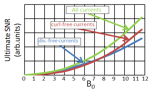
At high and ultra-high magnetic field strengths, understanding interactions between tissues and the electromagnetic (EM) fields generated by RF coils becomes crucial for safe and effective coil design as well as for insight into limits of performance. Mode expansion of dyadic Green’s functions (DGF’s) can be used to characterize the EM fields produced in a dielectric object 16, 17. For a given phantom of specific diameter, dielectric properties and the RF frequency using the DGF frame work we can calculate the ultimate intrinsic SNR (UISNR) and SAR 16. The fields associated with a complete basis set of current modes are combined using a matched filter to determine UISNR. These current modes can be separated into divergence-free and curl - free modes. At low fields UISNR is dominated by divergence - free current modes. And it is possible to approach UISNR by using dense loop arrays. However at 7.0 Tesla and higher field strengths curl-free current modes show an increasing contribution to UISNR (Fig.1). Hence to achieve optimal performance at ultra high fields a RF coil array needs to incorporate elements which can support curl-free and divergence-free currents.
There is a fundamental connection between loops and divergence-free current modes, and the fields produced by a loop element can be realized by using a basis set of divergence - free current modes. Curl-free current modes have been typically referred to as “dipole-like” currents16, 17 since the electric conduction currents in an electric dipole flow in a straight line with strong divergence and convergence near the ends. Work by Wiggins et.al used a combination loop and electric dipole elements and demonstrated significant SNR boost in a body sized phantom at 7.0T 18, initially thought to confirm this assumption. However, it should be noted that evaluation of an off-center loop in the Maxwell circuital equations, the currents and electric fields of an electric dipole antenna are not curl-free. Recent work by Sodickson et.al showed that a particular combination of curl-free and divergence-free currents is required to model an electric dipole antenna in DGF formalism 19. Instead of separating current modes into curl-free and divergence-free this work considers them as z-directed and Φ-directed current modes and compares dipole antennas to z-directed current modes.
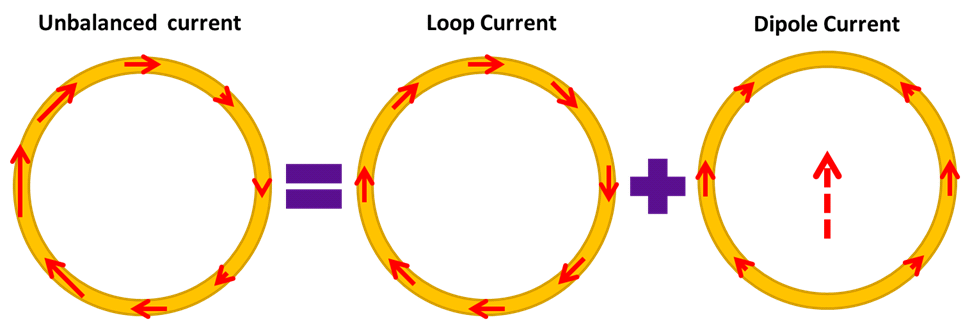
Ideal current patterns were the motivation behind the invention of the hybrid “Loopole” element. The loopole is a loop element with a non-uniform current distribution. A loop coil with uniform current is equivalent to a magnetic dipole. However when the current is not uniform a combination of curl-free and divergence-free current modes are required to realize the fields produced (Fig.2). By deliberately creating an unbalanced surface current distribution an electric dipole like mode is added on to a loop coil. Recent work has shown that an eight channel loopole array demonstrated improved transmit efficiency and SNR benefits when compared to loop array of similar dimensions20.
Alternative Design Approaches
UHF imaging has led to the emergence of field propagation and radiation concepts. These include
Travelling Wave Imaging: Brunner et.al proposed Travelling wave imaging to create a homogenous B1+ field over a large volume 21. The basic principle of the Travelling wave MRI is to excite the electro-magnetic modes available in the hollow conductive RF shield present in UHF scanners. These modes can be effectively excited by use of patch antennas, electric, or magnetic dipoles which are located at the bore end or at the isocenter 21, 22, 23. This approach proved that MR signals can be excited and received by propagating waves.
Radiative (Dipole, Stripline) Elements: Raaijmakers et.al introduced dipole antennas for human torso application 24. The importance of the complex poynting vector as an evaluation measure for effective RF energy flux was also demonstrated. To control SAR distribution high permittivity spacers were inserted between the antenna and human body. A similar design using bow-tie dipoles was introduced by Winter.et.al 25. Dipole elements are seeing increased use as transmit/receive elements in UHF coil arrays. Also a number of variations of electric dipole antennas have been successfully demonstrated 26, 27, 28.
UHF Array Design
UHF Array Design: A number of design issues have to be
considered while designing an UHF array. In order to achieve consistent and
safe performance the individual array coil elements have to be accurately
characterized and calibrated. This includes accurate measurements of coil
matching and tuning and a clear understanding of inter element interactions all
of which are load dependent. Various coil decoupling methodologies can be used
to minimize inter element interactions. It is important to note that available
decoupling methods depend on the type of element used in the coil array. Also,
the transmit field pattern of each element should be known; this knowledge is
often obtained in vivo with B1+ mapping techniques, but
unfortunately these techniques still have limitations for certain applications.
Safety Considerations
For any coil or array design, the SAR distribution of the coil array needs to be accurately characterized before use in vivo. While experimental maps of temperature increase in phantoms can be used to ensure safety in some cases, the flexibility in field distributions of a transmit array lead to a wide range of possible E-field and, ultimately, SAR distributions. To understand and assess the SAR for any combination of amplitude and phase in a transmit array, the field distributions of the individual coil elements should be evaluated in a heterogeneous body model for each of the phase and magnitude settings. This topic is beyond the scope of this talk, but has been addressed extensively elsewhere.Acknowledgements
No acknowledgement found.References
1. Edelstein WA., et al., - The intrinsic signal-to-noise ratio in NMR imaging. Magn. Reson. Med. 1986; 3(4): 604–618.
2. Robitaille PM., et al., - Ultra high resolution imaging of the human head at 8 tesla: 2K × 2K for Y2K. J. Comput. Assist. Tomogr. 2000; 24(1): 2–8
3. Bottomley PA., et al., - RF magnetic field penetration, phase shift and power dissipation in biological tissue: implications for NMR imaging. Phys Med Biol 1978; 23: 630–643.
4. Keltner JR., et al., - Electromagnetic fields of surface coil in vivoNMR at high frequencies. Magn Reson Med 1991; 22: 46–480.
5. Barfuss H., et al., - In vivo magnetic resonance imaging and spectroscopy of humans with a 4 Tesla whole body magnet. NMR Biomed 1990; 3: 31–45.
6. Bomsdorf H., et al., - Spectroscopy and imaging with a 4 Tesla whole-body MR system. NMR Biomed 1988; 1: 151–158.
7. Glover GH., et al., - Comparison of linear and circular polarization for magnetic resonance imaging. J Magn Reson 1985; 64255–270.
8. Duensing., G.R., et al - Transceive Phased Array Designed for Imaging at 3.0T. Proceedings of the 6th Annual Meeting of ISMRM, 1998: p. p 441.
9. Boskamp, E.B., et al., - Whole Body LPSA transceive array with optimized transmit homogeneity. Proceedings of the 10th ISMRM, Honolulu, Hawaii, USA, 2002: p. 903.
10. Vaughan, J.T., "RF Coil for Imaging Systems ", US Patent 6,633,161, 2003.
11. Vaughan, J.T., et al., "Parallel Transceiver for Nuclear Magnetic Resonance System", US Patent 6,969,992, 2003.
12. Hoult, D.I., et al., The NMR multi-transmit phased array: a Cartesian feedback approach. Journal of Magnetic Resonance, 2004. 171(1): p. 64-70.
13. Adriany, G., et al., Transmit and receive transmission line arrays for 7 tesla parallel imaging. Magnetic Resonance in Medicine, 2005. 53(2): p. 434-445.
14. Katscher, U., et al., Transmit SENSE. Magn Reson Med, 2003. 49(1): p. 144-50.
15. Zhu, Y., Parallel excitation with an array of transmit coils. Magn Reson Med, 2004. 51(4): p. 775- 84.
16. Lattanzi R., et al., MRM 68:286–304 2.Schnell W. (2000), IEEE Trans Ant Prop 48:418-28
17. Schnell W., et al., (2000), IEEE Trans Ant Prop 48:418-28
18. Wiggins G.C., et al., Proc. ISMRM 2013 p2737.
19. Sodickson D.K. et.al., Proc. ISMRM 2016 p389
20. Lakshmanan K., et al., Proc. ISMRM 2014 p397.
21. Brunner D.O., et al., Travelling-wave nuclear magnetic resonance. Nature, 2009. 457(7232): p. 994-998.
22. Brunner D.O., et al., Traveling-wave RF shimming and parallel MRI. Magnetic Resonance in Medicine, 2011. 66(1): p. 290-300.
23. Wiggins G.C., et al., Proc. ISMRM 2010 p429
24. Raaijmakers, A.J., et al., Design of a radiative surface coil array element at 7 T: Magnetic Resonance in Medicine, 2011. 66(5): p.1488-97.
25. L. Winter et al. Design and evaluation of a hybrid radiofrequency applicator for magnetic resonance imaging and RF induced hyperthermia... PLoS One 2013;8(4)
26. Lakshmanan K., et al., Proc. ISMRM 2014 p315
27. Alon L., et al., Proc. ISMRM 2016 p3516
Figures