Dielectric Materials & Resonators
1Radiology and Neurosurgery, Penn State College of Medicine, Hershey, PA, United States, 2Radiology, Penn State College of Medicine, Hershey, PA, United States
Synopsis
This talk will review and explain the dielectric effects in MRI using simple examples. Its applications in enhancing RF field using ultrahigh dielectric constant materials at 1.5T, 3T and 7T will be presented.
Specialty Area
Dielectric Materials & Resonators
Highlights
- a significant enhancement of SNR (50-200%) and drastic transmission power reduction (Multiple-fold) at 3.0T and 1.5T
- Reduction of total and local SAR for rapid imaging and low γ-nucleus applications.
Target Audience
MRI application scientists, MRI physicists, MRI hardware and RF engineersOutcome/Objectives
- Understand the effect of high dielectric constant (HDC) materials on RF field.
- Introduce ultrahigh dielectric constant (uHDC) materials for RF engineering for lower field MRI systems and / or low-γ nuclear applications.
Purpose
Incorporation of high dielectric constant (HDC) materials into radiofrequency (RF) coils has been shown to effectively improve RF coil performance at 7.0 and 3.0T as a result of the induced displacement current in the HDC materials (1-4). Since the displacement current is proportional to the RF field frequency and permittivity of the material, we would like to explore higher permittivity materials that can produce a greater RF field enhancement in lower static magnetic field strengths (1.5 and 3.0T) or low-γ nuclear applications at high field (7.0T). These materials are normally in the form of monolithic ceramics, referred as ultrahigh dielectric constant material (uHDC) materials.Methods
The RF magnetic field distribution is generally described by the Maxwell’s equations, mainly:
\[ \oint_LB_1\cdot{\text{d}l}=\mu\int\int_A\sigma E\cdot{\text{d}S}+\mu\frac{\partial}{\partial t}\int\int_{A} \epsilon_r\epsilon_0 E\cdot {\text{d}S}\] Ampere's Law [1]
\[ \oint_LE\cdot{\text{d}l}=-\frac{\partial}{\partial t}\int\int_SB_1\cdot{\text{d}S}\] Faraday's Law [2]
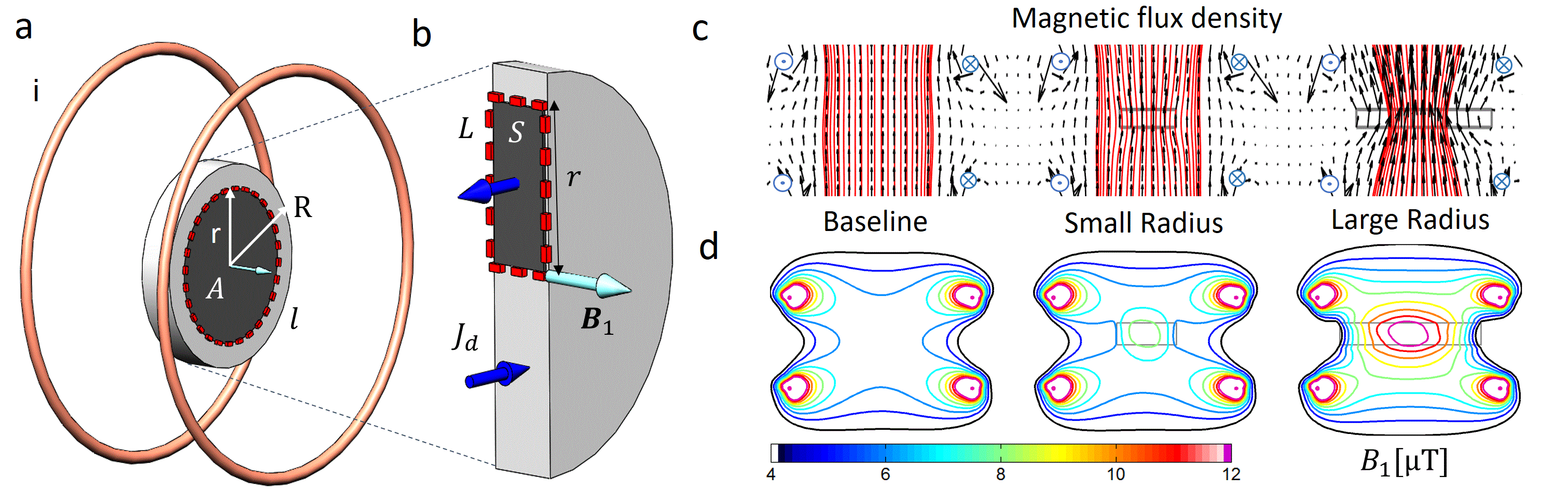
where B1 and E are the magnetic flux density and electric field strength of the RF field, respectively, σ is electrical conductivity,εr is relative electric permittivity or dielectric constant and ε0 is permittivity of free space. These two coupled equations must be solved simultaneously. The first term on the right side of Eq. [1] (σE) is conductive current density, Jc , and the second term \[\frac{\partial }{\partial t}\epsilon_r\epsilon_0E\] is the displacement current density, Jd. To illustrate the uHDC effect on the B1 of the RF coil, these equations are applied to a simple example as shown in Fig. 1a and b where an analytical solution can be derived. Experimentally, several monolithic ceramic materials with ultrahigh dielectric constant (uHDC) ranging from 1200 to 3300 were investigated at 1.5 T and 3.0 T for 1H, and 7T for 31P with phantom and human brain imaging along with computer modeling.
Results
As indicated in the Fig. 1c-d, B1 flux of the RF coil is focused by the uHDC disks. With a larger radius, this effect is stronger as it captures more B1 flux lines generated by the coil. A high B1 field plateau is created in and near the uHDC disks. Experimental measurements in phantom studies showed a significant enhancement of SNR (50-200%) and drastic transmission power reduction (3-27-fold). Under sub-optimal experimental conditions in this study, the SNR in the human brain cortex was nearly doubled, which produced similar high-resolution image quality as that obtained at 7.0T without the associated stronger magnetic susceptibility artifacts and elevated SAR concerns.Discussion
Using uHDC material with permittivity up to 1200 for 125 MHz at 3.0T for 1H and 7.0T for 31P, it is demonstrated a significantly greater RF field enhancements than previous studies using water-based high dielectric materials with permittivity of several hundreds. However, there should be an optimal permittivity for B1 field enhancement for a given operating frequency. Future development of customized uHDC materials with optimal permittivity and geometry for a give RF field frequency can further improve the B1 enhancement (5-7). With further development of customized uHDC materials for applications at operating frequency with reduced dielectric loss, the SNR can be further improved to levels close to theoretical predication. Another related issue is the space occupied by and the weight added to the RF coil could introduce some practical utilization issues. Thus, to maximize the benefits and minimized these impeding issues, several lines of future investigations should focus on finding an optimal combination of formulations and geometries of uHDC materials with customized RF coil design.Conclusion
Experimental results and theoretical analysis showed that remarkable improvements in RF transmission efficiency and image SNR can be achieved using uHDC materials, which can significantly benefit MRI research as well as clinical applications. Under sub-optimal conditions, the SNR in the human brain cortex could be doubled, which produced similar high-resolution image quality as that obtained at 7.0T without issues of stronger magnetic susceptibility artifacts and elevated SAR concerns.Acknowledgements
No acknowledgement found.References
Yang QX, Mao W, Wang J, et al.: Manipulation of image intensity distribution at 7.0 T: Passive RF shimming and focusing with dielectric materials. J Magn Reson Imaging 2006; 24:197–202.
Haines K, Smith NB, Webb AG: New high dielectric constant materials for tailoring the B1 + distribution at high magnetic fields. J Magn Reson 2010; 203:323–327.
Yang Q, Wang J, Wang J, Collins C: Reducing SAR and enhancing cerebral signal-to-noise ratio with high permittivity padding at 3 T. Magn Reson 2011.
de Heer P, Brink WM, Kooij BJ, Webb AG: Increasing signal homogeneity and image quality in abdominal imaging at 3 T with very high permittivity materials. Magn Reson Med 2012; 68:1317–1324.
Teeuwisse WM, Brink WM, Haines KN, Webb AG: Simulations of high permittivity materials for 7 T neuroimaging and evaluation of a new barium titanate-based dielectric. Magn Reson Med 2012; 67:912–918.
Yang Q, Rupprecht S, Luo W, Sica C: Radiofrequency field enhancement with high dielectric constant (HDC) pads in a receive array coil at 3.0 T. J Magn 2013
Luo M, Hu C, Zhuang Y, Chen W, Liu F, Xin SX, Numerical assessment of the reduction of specific absorption rate by adding high dielectric materials for fetus MRI at 3 T. Biomed Tech (Berl). 2016 Aug 1;61(4):455-61. doi: 10.1515/bmt-2015-0171.
Figures