Volume & Surface Coils
Synopsis
RF coils (antennas) for MRI are designed to generate a RF magnetic field inside the patient. Large body volume coils are optimized for the generation of a homogeneous RF magnetic field. Local surface coils are designed to provide high signal to noise ratio. Different designs and related physical aspects are discussed.
Introduction
In nuclear magnetic resonance imaging (MRI) radio frequency (RF) signals establish a bi-directional link between the MRI system and the patient [1]. The clinical MRI systems of today operate at static magnetic field strengths Bo between 0.2 Tesla and 3 Tesla with proton resonance frequencies between 8 MHz and 130 MHz. RF coils for MRI are designed to generate a magnetic field inside the patient. Only the negative (for reception) and positive (for transmission) rotating magnetic field components contribute to the imaging process. All other fields, like ~B0-directed magnetic fields or electric fields have to be avoided as much as possible since they reduce the coils sensitivity. Particularly the electric fields can be dangerous because these are responsible for absorption of energy in the patient, resulting in heating up the tissue. Energy absorption in transmit coils corresponds to noise generation in receive coils, thus also receive coils have to be designed such, that they generate low electric fields in case they would be used for transmission. The RF-frequency increases with the static magnetic field strength B0. At least, if the coil dimensions become comparable to the wavelength inside the patient, propagation effects have to be included in field simulations. In order to select the correct coil, the characteristics of the volume of interest (VOI) is crucial. For whole body scans the standard design of the birdcage coil is a convenient choice, whereas a surface coil is more suitable for small regional scans, the head coil is preferred for taking images of the brain.Electromagnetic field of the RF Coil
The efficiency of RF coils for MRI systems in terms of optimal spin excitation and maximised SNR is strongly influenced by the RF electromagnetic field interaction with the human body as a load to the coil [2-6]. The degree of coil loading is subject to the large variation in sizes of the patient population ranging from babies to male or female adults with slim, normal or corpulent stature and body weights from 3 kg up to about 120 kg. For MRI systems with B0 > 0.5 T the Larmor frequency is > 21 MHz. In this range the onset of dielectric effects associated with the high value of the permittivity εr ~ 60 to 100 of the body tissues is observed. As result, the wavelength in the body is comparable with the body dimensions and, at higher frequencies the increasing effect of the B1 eigenfield modifies the B1 field generated by the RF coil inside of the body [1]. Furthermore, eddy currents due to the conductivity σ ~ 1 S/m of body tissues reduce the penetration of the B1 field into the body at higher frequencies (Fig1a). Assuming an average relative dielectric constant of εr = 50, the wavelength is about 33cm for 3T-systems or 14cm for 7T systems (Table 1). Predictions on RF coil performance must therefore be based on studies of the coil with patient loads. Mimicking this condition by phantoms provides at best an incomplete evidence of the real performance. A theoretical treatment of the complicated RF boundary problems as given by the patient loaded RF coils requires the application of numerical methods [7]. The method of moments offers a fast simulation technique that includes propagation effects. It is based on the electric and/or magnetic field integral equations (EFIE, MFIE). The structure (but not the free space) is separated into sections small compared to wavelength (and skin depth in case of dielectric bodys as-well). The (electric and/or magnetic) currents on the structure are discretized in so-called base functions and the total current can be described by a linear combination of these base functions. By using given boundary conditions, a set of linear equations is compiled to solve for the unknown base function weighting factors. After solving this with standard iterative or direct solving methods, the electric and magnetic fields is calculated by integral equations. A patient model can be incorporated by equivalent currents on the surface or inside the tissue. Fig. 1c shows the magnetic field inside a homogeneous human head model at 7T calculated by the Method of Moments [8]. Due to resonance effects in the patient model, the field is much less homogeneous compared to the unloaded case [12, 13]. The FDTD method is based on a finite difference approximations in space and time that solves Maxwell’s time dependent curl equations and widely applied for EM simulations in MRI [9,10]. If the FDTD simulation is fed by an impulse response, the result after Fourier transformation yields information on the RF properties of the model over a wide frequency range. The smallest detail of the simulated RF coil model geometry typically dictates the requirements of the equal-distance cubical grid size, resulting in very long computation times. This makes the method less suitable for RF coil design, but suitable for the verification process. Therefore, the method is widely used for characterization of the local absorption (SAR) inside a high resolution dielectric model of the human body (see Fig.1d). The finite difference method divides the object into (interleaved) cubical cells, thus it cannot accurately model arbitrary geometries. This disadvantage is overcome by the finite element method, which divides the region of interest into irregular tetrahedron cells. Since the size and orientation of these cells can be arbitrary, the finite element method can accurately model arbitrary geometries [11].RF Coil Characteristics
RF coils, as first part of the RF chain, have a severe impact on the final signal-to-noise (SNR) level. The equivalent measure of the SNR for transmit coils is the B1 power sensitivity SP. The power sensitivity is defined by the amount of power P0 required to produce a certain field strength at a reference point, typically at the isocenter of the unloaded coil [2],
$$S_{PO}=\frac{\hat{B}_1}{\sqrt{P_0}}$$
The power sensitivity of the loaded coil is
$$S_{PI}=\frac{\hat{B}_1}{\sqrt{P_P+P_O}}=S_{P0}*\sqrt{\frac{Q_l}{Q_o}}$$
with the power P0 dissipated in the resistance R0 of the unloaded coil and the power PP dissipated in the equivalent resistance RP of the patient or phantom. The power sensitivity SPI also be expressed in terms of the unloaded and loaded Q-factors. The Q‑factor $$$Q=\frac{\omega L}{R}$$$ is an inverse measure of the RF losses in the coil with ωL being the reactive and R the resistive part of the impedance of the coil. The losses of the unloaded coil, modeled by a series resonant circuit, R0, are caused by the equivalent series resistance of the capacitors and by the resistance of the conductor structure. The RF losses induced in the patient add a further component RP to the resistive part of the coil impedance. The resistance R0 can be minimized by a careful design of the coil; however, the resistance RP, determined by the patient, can (e.g.) be reduced by restricting the FOV seen by the coil. The load factor$$$LF =\frac{Q_0}{Q_l}$$$ is the ratio between the quality factor QO of the unloaded coil and the quality factor Ql of the loaded coil. The power efficiency η of the coil can be expressed using the load factor, the powers or the resistances
$$\eta=\frac{P_{P}}{P_{0}+P_{P}} =\frac{LF-1}{LF}=\frac{R_P}{R_P+R_0}$$
The power efficiency of the coil increases with the load factor LF. The load factor is sufficiently high, if the loading effects dominate and the resistance of the coil structure is negligible. Then, the noise results from the presence of the patient and the RF coil itself does not notably increase the noise level. Applying the analogy for transmission and reception, the transmitted power is predominantly dissipated in the patient and not in the RF coil. The load factor of an MRI coil can be influenced by the design of the coil and the placement of the coils with respect to the RF screen and the load. Within the patient load exposed to the B1 field of the RF coil, the principal RF loss and thus for MRI irreducible contribution arises from the electric fields which are magnetically induced in the different conductive body tissues. However, the interaction of the unavoidable electric fields in the RF coil structure with the patient load cause an additional loss contribution, which can be minimized by increasing the self-resonance frequency of the coil with additional series capacitors in the coil conductors. The sign and the value of the relative frequency shift, $$$\triangle f_l/f_0 =(f_l - f_0)/f_0$$$, observed when the RF coil is loaded by the patient, characterise the contribution from the residual RF electric fields in the coil to the RF absorption in the patient in terms of unwanted dielectric losses [2]. The dielectric loss contribution is negligible when Δfl/f0 is positive, i.e. the resonance frequency of the RF coil rises slightly when the patient is inserted. Since the RF loss induced by the transversal B1 field in the patient is irreducible in MRI, high efficiency of the RF coil requires a high value of the ratio Q0/Ql . Obvious goals are a high Q0 together with a low value of Ql, which requires strong coupling to the patient load using low impedance RF coils. Typical values for the Q factor range in MR coil design from QL = 100 (loaded) to QO=400 (unloaded), e.g. measured on a phantom for the first and in air for the latter.
RF Coil Measurements
The RF loss contributions of the RF coil and of the patient load can be found from measured values of the resonance frequencies and the Q‑factors for the empty coil, f0, Q0, and for the coil with patient load, fl, Ql. The quality factor of a resonant coil can be measured using a single pickup-coil connected to a network analyzer [14,15,16]. Fig. 2a shows the schematics of a pickup coil, coupling to a series resonant circuit. The network analyzer can be short-calibrated for M= 0 to compensate for the pickup-coil impedance jωLPU. Assuming a low coupling M and a not too low quality factor Q, the reflection at the so called 3dB-frequencies provides the quality factor Q=ω0/Δω. The 3dB-frequencies can be found using the logarithmic display on a network analyzer (Fig.2c). If the 0dB line is placed at the top of the display and the scaling is chosen such that the resonance peak just hits the bottom, than the curve displayed intersects the center line at the 3dB-frequencies as shown in Fig.2b. With the power absorbed in the resonator $$$P=\frac{1}{2} R |I_{coil}|^2$$$ the power sensitivity is given by $$$S_P =B_1 /\sqrt{P}$$$. The power sensitivity can be obtained from a transmission measurement. The sensitivity SP obtained by a transmission measurement (Impedance of cable Z0, area of pick up coil APU, Inductivity of pick up coil LPU) is given by:
$$S_p =\frac{\sqrt{2 Z_o}}{\omega A_{PU}}|S_{21}|\sqrt{\frac{1+(\frac{\omega L_{PU}}{Z_o})^2}{1-|S_{11}|^2}}$$
If the coil to be tested already has a feeding port, it can be connected to the network analyzer (Fig.7). Alternatively, the coil can be fed by a separate pickup-coil. The second port of the network analyzer is connected to a receiving pickup-coil which is placed at that point where SP is to be determined. The network analyzer radiates a power Pnwa,out into the cable connected to its port 1. Neglecting losses in the pickup-coil 2, the power $$$P_{coil} = P_{nwa,out} (1-|S_{11}|^2)$$$ reaches the MRI-coil. Always cable losses have to be calibrated out. If there are significant losses in the pickup-coil, these also have to be considered.
Volume Coils
Ideal volume coils for MRI use with a human body, head or limb have cylindrical symmetry, sample access from one or both sides and should provide a uniform transverse magnetic B1 field. A uniform transverse magnetic field can be generated by an axial current flow with cosine current distribution around a cylinder wall. For practical applications, the continuous wall current sheet can be approximated by N equiangular spaced discrete current rods. This cylindrical N‑conductor structure forms a transmission line which propagates transverse electromagnetic (TEM) modes r, with $$$1\leq r \leq N/2$$$ for the unshielded structure and $$$0\leq r \leq N/2$$$in the presence of an external coaxial shield, where the current distribution in the rods numbered $$$i =1,2,..,(N-1),N$$$ is given by:
$$I_i,_r = I_0 cos [ (i-1)r2\pi/N]$$
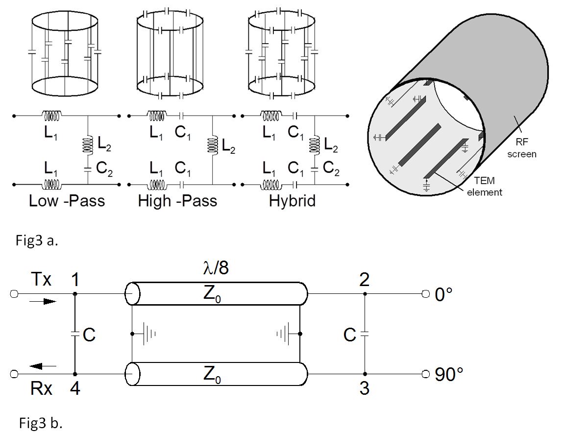
The r = 1 mode provides the required homogeneous transverse magnetic field for applications in RF coils, where a short section of the N-conductor TEM transmission line [17,18,19] is terminated at both ends with suitable reactances to establish resonance. Principally, there are two methods of terminating the TEM section, which differ in the paths of the RF currents outside the N‑conductor section. Hayes et.al. [20] introduced the birdcage structure with ring sections interconnecting all rods at both ends as termination of the TEM line section and with tuning capacitors applied in series to the rods (low-pass) or to the ring sections (high-pass) or to both positions (band-pass). Here the rod currents accumulate in the ring to high values depending on N, and the inductances of the ring sections strongly influences the separation of the resonance modes. Tropp [21] presented an extended theory of the birdcage resonator and of the involved mutual inductances in the unshielded and shielded TEM line sections. Depending to the placement of the tuning capacitors in series to rods, to rings, or to both, the birdcage structure [22] is called low-pass, high-pass, or band-pass (Fig.3a). The mutual coupling between the conducting rods and rings and the selection of the capacitor values result in multiple resonant modes. According to the current distribution, each of the modes generates different distributions of the electromagnetic field. The desired cosine-shaped current distribution is achieved by adjustment of the resonance frequency of the mode generating the homogeneous field. The whole body transmit coil is located inside a cylindrical RF screen, to provide a defined RF environment. Without the RF screen, the coil strongly couples with the gradient coil and reduces the performance of both coils. The cylindrical RF shield is transparent (high impedance) for the gradients to prevent eddy currents and impermeable (low impedance) for RF to reduce losses during transmission and interfering signals during reception.
Matching the Coil
MR transmit coils are matched to the impedance of the RF chain (50Ω) in order to avoid power reflection, and thus, to decrease power efficiency [23, 24]. Generally, an RF coil exhibits a complex impedance, so that a matching network with at least two degrees of freedom is required. Preferably, the matching is achieved with capacitors, as capacitors are available over a wide range in a compact shape and do not generate magnetic stray fields by themselves.Driving the coil in quadrature
The desired circularly polarized RF field is achieved by driving the body coil in quadrature mode. The quadrature drive of a cylindrical body coil requires the existence of two input ports, which have to be driven by two input RF signals with 90o phase difference [25,26,27]. A quadrature hybrid splits the Tx input signal at port1 (Fig.3b) to the ports 2 and 3. During reception, the receive signals are combined and appear at port 4. The ports have to be connected with respect to the static magnetic field B0, so that the rotation direction is in the same direction as the Lamor precession. A quadrature combiner can have several tenths of a dB of insertion loss, lowering the overall noise figure of the receiver correspondingly. Hybrids for lower frequencies can be realized easily using lumped element components. In the quadrature hybrid, the reflected waves are cancelled, if the mismatched load is symmetric.Multi Channel Transmit and Receive Coils
At field strengths higher than 3T, wave propagation effects (sometimes called “dielectric resonances”) represent a primary cause of RF field inhomogeneities in body MR imaging. RF shimming techniques, based on multi-channel RF transmit technology [28-31], bear the potential of compensating these RF field inhomogeneities. Furthermore, parallel transmission systems allow advanced imaging techniques, in particular the acceleration of multi-dimensional RF-pulses [32,33]. The transmit coil consists of a degenerate birgcage [34,35] loops [36] or a degenerate TEM coil [37,38], in which the individual coil elements are decoupled from another. Each individual decoupled coil element is driven by an individual RF source. A method to protect the RF power amplifiers against reflected and coupled power from the coil elements is to locate circulators between coil and amplifiers. Each channel can be controlled individually in amplitude and phase in order to create spatio-temporal variations of the B1- field, which in sum with the propagation effects cause the desired RF field.Receive Coils
During the acquisition, the induced voltage, caused by rotating spins, is detected by an RF receive coil and is stored in memory. After acquisition has finished, linear transformation (Fourier transformation) produces the final MR image from the sampled voltage values. Thus, the data of the final image is proportional to the detected voltage, which itself is a superposition of signal from spin and noise. The SNR relates the voltages of noise and spin [40-43]:
$$\frac{S}{N} (r) =\frac{\omega V\mid M * \frac{B(r)}{I}\mid}{\sqrt{8kT\triangle f (R_A +R_L )}}$$
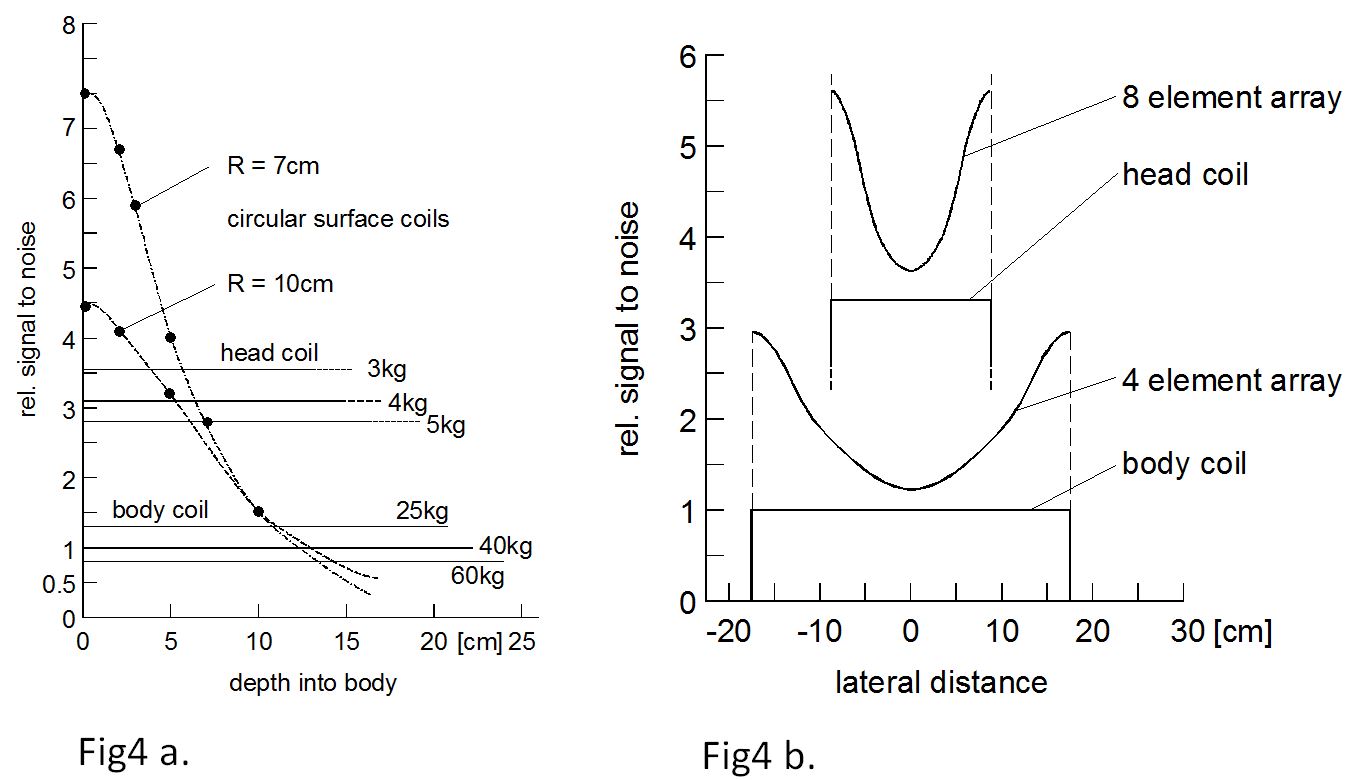
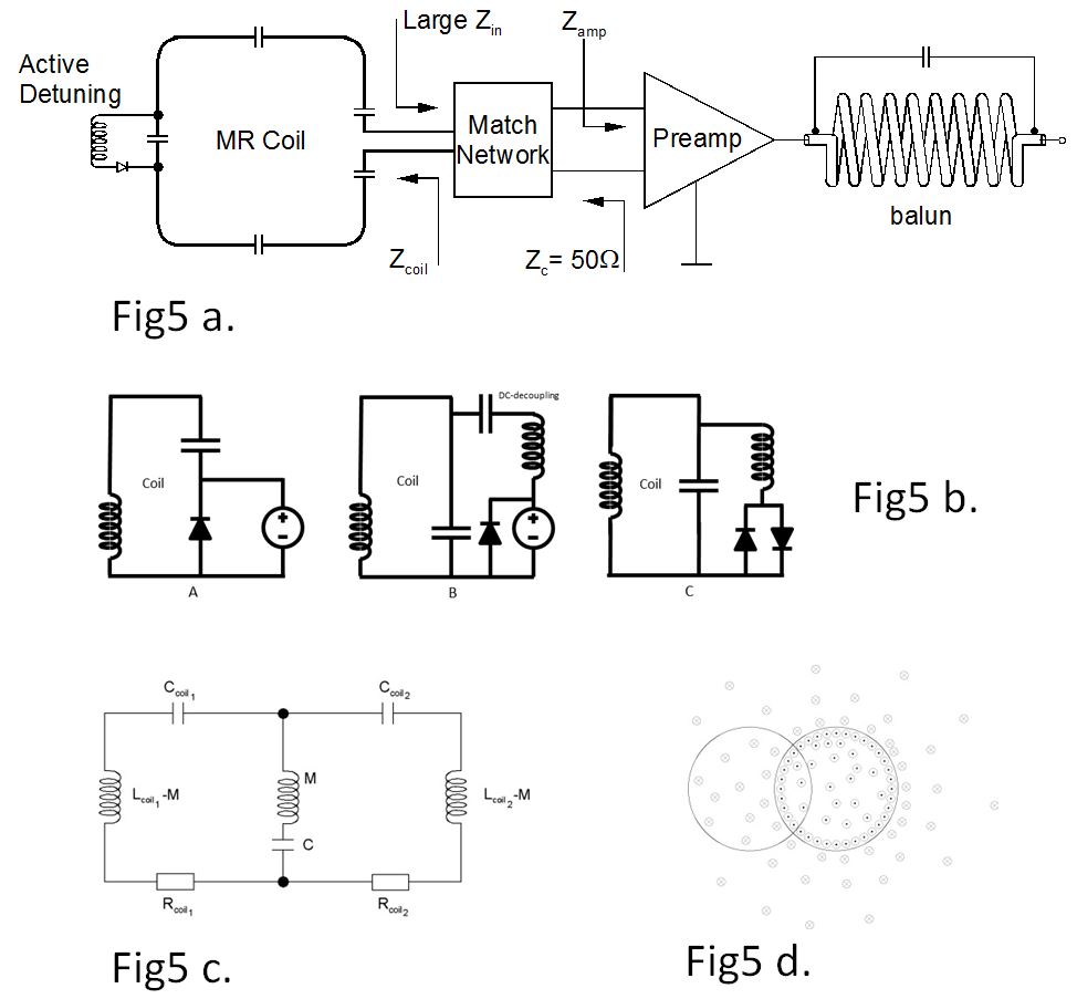
The spin signal (numerator) is proportional to the frequency w, the considered Volume V, the nuclear magnetization M, and the magnetic flux density B in the point r in space produced by the current I. The resistors RA (antenna loss) and RL (load loss), the bandwidth Df and the temperature T dictate the noise (denominator). The noise of a well-designed MR coil must not be dominated by the antenna loss.The signal-to-noise ratio attainable with a MR receive coil is inversely proportional to the effective coil losses. It has been shown that these resistive losses are proportional to the patient volume illuminated by the coil [44-45]. The losses of the unloaded coil, R0, are caused by the resistance of the conductor structure and the equivalent series resistance of the capacitors. The RF losses induced in the patient add a further component RP to the resistive part of the coil impedance. The resistance R0 can be minimized by careful design of the coil; however, the resistance RP, determined by the patient, can only be reduced by restricting the FOV. Hence, for dominating patient losses, the SNR is nearly inversely proportional to this patient volume. Depending on the application, the region-of-interest (ROI) encompasses only a fraction of the total patient volume seen by the coil. Consequently, the noise induced is larger than the value corresponding to the ROI if a body sized coil is used. Therefore, dedicated coils were introduced to improve the SNR (see Fig.4a). Receive coils, designed for certain parts of the human body are called surface coils due to their placement directly on the patient. A single receive coil as depicted in Fig.5a consists of the conductor structure, which is optimized for the dedicated imaging application. Distributed series capacitors along the conductor provide equal current distribution and reduce dielectric losses. Preamplifiers are necessary to boost the extremely weak signal. The preamplifier should be in close proximity of the coil so that additional components do not diminish the performance. The best noise figure is achieved if the matched coil presents the so-called optimum noise impedance to the preamplifier. This impedance is realized by transforming the impedance of the coil via a low loss matching network to the optimum noise impedance of the preamplifier [47,48].
Coil Detuning
The RF receive coil elements are optimized to resonate at the MR frequency. During excitation of the nuclear spins, a strong RF field is applied in the same space as where the receive coil resides. Without any counter measures the current in the receive coil elements would rise to unacceptable high levels To overcome this problem, the receive coil elements are switched to detune state during the transmission of the RF excitation pulse [49,50]. Circuits that prevent or reduced current flow in the coil element as a result of an induced RF voltage are shown in Fig 5b. If the MR system is in receive mode, the detuning circuit prevents inter-element or inter-coil coupling. If the MR system is in transmit mode, the detune circuit must prevent distortion of the B1 excitation field. The detune circuit is an important component for patient safety. It prevents exceeding the local SAR limits.Coil Cable and RF Trap
Typically a coaxial cable connects the preamplifier to the rest of the RF chain. The coil elements are magnetically and electrically coupled with the transmit coil. The coil as a whole or the cable on its own can act like an antenna. If this is the case, energy is withdrawn from the transmit coil and the intended homogeneity of the transmit coil is compromised. The common mode current on the cable itself is a source of magnetic field surrounding the cable. This locally changes the magnitude of the magnetic field and hence the flip angle of the excitation. The shield of the cable has to be of high impedance for currents induced by the transmit field to avoid imaging artifacts and heating. Among other solutions, parallel resonant baluns with high impedances are used to minimize the RF currents on the shield [51, 52].Decoupling of RF Coils
It is common practice to describe two coupling coils using an equivalent circuit diagram. In this diagram the inductive coupling is represented by a mutual inductance on a common path. It is obvious, that for decoupling this shared inductance has to be compensated by an additional capacitor [53,54]. The value of the capacitor must yield the same impedance as the inductance does (Fig5c). Since this condition can be satisfied only for a single frequency, capacitive decoupling is always narrowband. Another way to reduce coupling is the idea to arrange adjacent coils in such a smart manner, that the integral flux through the surface of a secondary coil caused by the primary coil vanishes (Fig5d). This can be done very simple for next neighbor coils overlapping them [55]. But the complexity increases using an array, which usually comprehends next-neighbor and non-next-neighbor coils. On the other hand, the coupling between non-next-neighbor coils is much less critical, therefore it is needful to check individually, if decoupling is mandatory.Receive Coil Arrays
The application of arrays [55] of several elements overcomes the limitation of the restricted FOV of a single surface coil and provides optimized imaging performance over large body areas (Fig.4b). The individual signals detected by the coil elements are fed to individual receiver channels. During reconstruction, the individual signals of these coils are combined, and a higher SNR is available for a large imaging volume. Arrays can be designed to be tight fitting to the body and effectively receiving from volumes smaller than a typical body volume coil. In case noise signals are coupled from one coil to the other, the SNR of the combined image is reduced. To prevent that such correlated noise diminishes image quality, the individual coil elements have to be mutually decoupled. Minimization of the coupling and noise correlation can be achieved by different strategies [55-59]. Next neighbor coil elements can be mutually decoupled using a defined element-to-element overlap, so that the mutual inductance is cancelled. However, this technique restricts the shape and the positioning of the elements, which limits the optimization of the coil for imaging parameters or body regions. Furthermore, the decoupling of the second next neighbors in an array of coils is challenging. Preamplifier decoupling provides effective decoupling of a coil from its neigbours. For optimum performance, the network shown in Fig.5a transforms the coil impedance ZCoil to 50 Ω to offer noise match at the input to the amplifier [60] and inversely transforms the amplifier input impedance ZAmp to a quasi open circuit Zin at the terminals of the coil. This method reduces coil currents, and thus, unwanted coupling effects between neighboring antennas. Ideally, the individual coils maintain their individual SNR as if operating as a single element. In advanced methods [61- 63], multi-element surface coils are used to encode the spatial information. These methods utilize the spatial dependence of the B1 field maps of the coils to accelerate the imaging process.Double Resonant Coils
In addition to proton imaging (which is the most abundant atom), other nuclei (such as 31P or 19F) are used as well, to quantify metabolic concentrations in neural or muscular tissues. Double tuned coils are used for imaging and spectroscopy at high fields. However, this requires dedicated MRI transmit and receive coils resonant at both frequencies and maintaining a good performance for both frequencys. 19F MR imaging has a high potential for the detection and direct quantification of fluor-labeled tracers and drugs in the field of molecular imaging [64, 67]. The combination with 1H imaging provides the associated anatomical information. Thus far, the integration of separate 19F and 1H RF coils has typically been used to support this application. The challenge is to provide virtually the same sensitivity profile for the two frequencies. This allows the correction of B1 inhomogeneities in the 19F image via the 1H sensitivity profile. TEM- and Birdcage designs exit using separate feeding ports for both nuclei [68-71].Acknowledgements
The author wish to acknowledge Christian Findeklee, Oliver Lips and Peter Vernickel for valuable assistance and helpful discussion.References
[1] Röschmann P. RF coil (Antennes) for MRI, Syllabus contribution, 16th ESMRMB 1999 [2] P. Roeschmann. Radiofrequency Penetration and Absorption in the Human Body: Limitations to High-Field Whole-Body Nuclear Magnetic Resonance Imaging. Med. Phys., 14(6):922–931, 1986. [3] J. T. Vaughan, M. Garwood, C.M. Collins, W. Liu, L. DeLaBarre, G. Adriany, P. Andersen, H. Merkle, R. Goebel, M. B. Smith, and K. Ugurbil. 7 T vs. 4 T: RF Power, Homogeneity, and Signal-to-Noise Comparison in Head Images. Magnetic Resonance in Medicine, 46:24–30, 2001. [4] T. S. Ibrahim, R. Lee, A. M. Abduljalil, B. A. Baertlein, and P.-M. L. Robitaille. Dielectric Resonances and B1 Field Inhomogeneity in UHFMRI Computational Analysis and Experimental Findings. Magnetic Resonance Imaging, 19:219– 226, 2001. [5] Q. X. Yang, J. Wang, X. Zhang, C. M. Collins, M. B. Smith, H. Liu, X.-H. Zhu, J. T. Vaughan, K. Ugurbil, and W. Chen. Analysis of Wave Behavior in Lossy Dielectric Samples and High Field. Magnetic Resonance in Medicine, 47:982– 989, 2002. [6] A. Kangarlu, B. A. Baertlein, R. Lee, T. Ibrahim, L. Yang, A. M. Abduljalil, and P.-M. L. Robitaille. Dielectric Resonance Phenomena in Ultra High Field MRI. Journal of Computer Assisted Tomography, 23(6):821–831, 1999. [7] Jianming Jin: Electromagnetic Analysis and Design in Magnetic Resonance Imaging; CRC Press 1997, ISBN 0-8493-9693-X [8] [CON] CONCEPT II: Method of Moments program of the Technical University of Hamburg-Harburg [9] TS Ibrahim et al Phys. Med. Biol. 46(2001) 609-619 [10] Karl S. Kunz, R.J. Luebbers, The FDTD Method for electromagnetics ISBN 0-8493-8657-8 [11] ANSYS HFFS Simulator [12] Leussler C. et al, ESMRMB Shielded Endcap Bandpass Resonator for Ultra High Field Imaging at 7 Tesla EPOS 389, 2004 [13] DeMeester G., Shoulder Shield for 7.0T T/R Brain Coil , et al, Proc. Intl. Soc. Mag. Reson. Med. 14 (2006) p. 2610 [14] Hoult,D.I., The NMR Receiver: A Description and Analysis of Design, Progr. NMR Spectr.,12, pp.41-77, 1978 [15] Ginefri, J.C. et al Quick measurement of nuclear magnetic Resonance Coil Sensitivity with a single loop probe, Rev. Sci. Instrum. 70,4730-4731,1999 [16] Chen, C.N. et al The field dependance of NMR Imaging.I. Laboratory Assessment of Signal-to Noise Ratio and Power deposition, Magn. Reson. Med.,3, 722-729, 1986 [17] Röschmann P. US patent 5160890, 1991. [18] Bridges J. Cavity resonator . U.S. Patent 4751464, 1988. [19] Chingas GC, Zhang N. Design Strategy for TEM high Field Resonators. Proceedings of the 4th Annual Meeting of ISMRM, New York, USA 1996: p.1426. [20] Hayes CE, Edelstein WA, Schenk JF, Mueller OM, Eash M. An Efficient, Highly Homogeneous RF coil for whole Body NMR Imaging at 1.5T. J Mag Reson 1985;63:622-628. [21] Tropp J. Mutual Inductance in the Bird-Cage. J Magn Reson 1997;126-1:9-17. [22] Röschmann P. Analysis of Mode Spectra in Cylindrical N-Conductor Transmission Line Resonators with expansion to Low-, High- and Band-pass Birdcage Structures. Proc. Intl. Soc. Mag. Reson. Med.1995;3: p. 1000. [23] P.L. Kuhns et al, “Inductive Coupling and Tuning in NMR Probes; Applications,” J. Magn. Reson. 78, 69-76 (1988) [24] ARRL Handbook of Radio Communications 86th edn. Wilson, M.J.(ed), American Radio Relay League, Inc. Newington, USA, 2009 [25] Jin J. Elektromagnetic Analysis and Design in MRI, CRC Press, New York, 1999. [26] Mispelter J, Lupu Mihaela L, Briguet A. NMR probeheads, Imperial College press, 2006. [27] Sorgenfrei B, Edelstein W. Optimizing MRI signal-to-noise ratio for quadrature unmatched RF coils. Magn Reson Med 1996; vol. 36:104-10. [28] Ullmann P, Junge S, Wick M, Seifert F, Ruhm W, Hennig J. Experimental analysis of parallel excitation using dedicated coil setups and simultaneous RF transmission on multiple channels. Magn. Reson. Med. 2005;54:994-1001. [29] Zhu Y, Watkins R, Giaquinto R, Hardy C, Kenwood G, Mathias S, Valent T, Denzin M, Hopkins J, Peterson W, Mock B. Parallel excitation on an eight transmit-channel MRI system. Proc. Intl. Soc. Mag. Reson. Med. 2005;13: p.14. [30] Setsompop K, Wald L, Alagappan V, Gagoski B, Hebrank F, Fontius U, Schmitt F, Adalsteinsson E. Parallel RF transmission with eight channels at 3 Tesla. Magn. Reson. Med. 2006;56:1163-1171. [31] Graesslin I, Vernickel P, Schmidt J, Findeklee C, Röschmann P, Leussler C, Haaker P, Laudan H, Luedeke KM, Scholz J, Buller S, Keupp J, Börnert P, Dingemans H, Mens G, Vissers G, Blom K,Swennen N, van der Heijden J, Mollevanger L, Harvey P, Katscher U. Whole body 3T MRI system with eight parallel RF transmission channels. Proc. Intl. Soc. Mag. Reson. Med. 2006;14: p.129. [32] Katscher U, Börnert P, Leussler C, van den Brink J. Transmit SENSE. Magn. Reson. Med. 2003;49:144-150. [33] Zhu Y. Parallel excitation. Magn. Reson. Med. 2004; 51: 775-784. [34] Leussler C, Stimma J, Röschmann P. The Bandpass Birdcage Resonator Modified as a Coil Array for Simultaneous MR Acquisition. ISMRM 1997; p. 176. [35] Alagappan V, Nistler J, Adalsteinsson E, Setsompop K, Fontius U, Zelinski A, Vester M, Wiggins GC, Hebrank F, Renz W, Schmitt F, Wald LL. Degenerate Mode Band-Pass Birdcage Coil for Accelerated Parallel Exitation. Magn Reson. Med. 2007;57:1148-1158. [36] Weyers DJ. Proc. Intl. Soc. Mag. Reson. Med. 2002; p. 901. [37] Leussler, C. Wo patent 02/095435, 2002. [38] Vernickel P, Röschmann P, Findeklee C, Lüdeke KM, Leussler C, Overweg J, Katscher U, Grässlin I, Schünemann K. Eight-Channel Transmit/Receive Body MRI Coil at 3T. Magn Reson. Med. 2007;58:381-389. [39] Vester M. Proc. Intl. Soc. Mag. Reson. Med. 2006; p. 2024. [40] D. I. Hoult. The Principle of Reciprocity in Signal Strength Calculations – A Mathematical Guide. Concepts in Magnetic Resonance, 12(4):173–187, 2000.[41] Schnell W et al Ultimate signal-to-noise-ratio of surface and body antennas for magnetic resonance imaging, IEEE Transactions on Antennas and Propagation (Volume: 48, Issue: 3, Mar 2000 ) [42] C. M. Collins and M. B. Smith. Calculations of B1 Distribution, SNR, and SAR for a Surface Coil Adjacent to an Anatomically-Accurate Human Body Model. Magnetic Resonance in Medicine, 45:692–699, 2001. [43] W. A. Edelstein, G. H. Glover, C. J. Hardy, and R. W. Redington. The Intrinsic Signal-to-Noise Ratio in NMR Imaging. Magnetic Resonance in Medicine, 3:604–618, 1986. [44] Hoult DI, Richards RE. The signal-to-noise ratio of the nuclear magnetic resonance Experiment. J Magn Res.1976;24:71-85. [45] Röschmann P, Tischler R. Surface coil proton imaging at 2 T 1986;Radiology 161:251-255. [46] Wang J, Reykowski A, Dickas J. Calculation of the Signal-to-Noise Ratio for Simple Surface Coils and Arrays of Coils. IEEE Trans. Biomed. Eng.1995;Vol. 42, No. 9:908-17. [47] Reykowski A, Wright SM, Porter JR. Design of Matching Networks for Low Noise Preamplifiers. Magn Reson Med 1995;33:848-852. [48] Findeklee C. Proc. Intl. Soc. Mag. Reson. Med. 2009;17:507 [49] Edelstein et al., Electronic decoupling of Surface-Coil Receivers for NMR Imaging and Spectroscopy1986, J. Magn. Reson.,67, 156-161. [50] Joel Mispelter, Mihaela Lupu, Andre Briguet, NMR Probeheads, Imperial College Press ISBN 978-1-84816-662-2, 2015 [51] R. Dean Straw. The ARRL Handbook for Radio Communications. ARRL-the National Association for Amateur Radio, 2006. [52] Seeber et al., Floating Shield Current Current Suppression Trap, Concepts in Magn. Reson., 21B, 26-31, 2004 [53] Wang J., Proc. ISMRM 4:1434 (1996) [54] Jevtic J., Proc. ISMRM 9:17 (2001) [55] Roemer, et al, The NMR Phased Array. MRM 1990;16:192-225 [56] Leussler C. and Holz D. (1991) Improvement of SNR at low field strength using mutually decoupled coils for simultaneous NMR imaging. Proc. 11th SMRM 1991;p.734. [57] Reykowski A. Theory and Design of Synthesis Array Coils for MRI, Texas A&M Univ., Dissertation, 1996. [58] Hutchinson M, Raff U. Fast MRI data acquisition using multiple detectors. Magn Reson Med 1998;6:87–91. [59] Kwiat D, Einav S. A decoupled coil detector array for fast image acquisition in magnetic resonance imaging. Med Phys 1991;18:251–265. [60] Reykowski A, Wright SM, Porter. JR Design of Matching Networks for Low Noise Preamplifiers, Magn Reson Med 1995;33:848-852. [61] Pruessmann KP, Weiger M, Scheidegger MB, Boesiger P. SENSE: sensitivity encoding for fast MRI. Magn Reson Med 1999;42:952-962. [62] Weiger M, Pruessmann K, Leussler C, Roeschmann P, Boesiger P. Specific coil design for Sense: a six element cardiac array. MRM 2001;45:495. [63] Sodickson DK , Manning WJ. Simultaneous acquisition of spatial harmonics (SMASH). Magn Reson Med 1997;38:591-603. [64] Morawski A et al., MRM 52:1255 (2004) [65] Gonen O et al., MRM 37:164(1997) [66] Krems B et al., Magn Reson B 108:155(1995) [67] Mazurkewitz et al EPOS 821 page 370-371 ESMRMB (2006) [68] X. Zhang et al.: A circular-polarized double-tuned (31P and 1H) TEM coil for human head MRI/MRS at 7T, Proc. Intl. Soc. Mag. Reson. Med. 11 234 (2003) [69] S. B. King et al.: A Comparasion of Double Tuned Birdcage and Spiral Birdcage RF Coils, Proc. Intl. Soc. Mag. Reson. Med. 11 (2004) 1559 [70] W. Dürr, S. Rauch: A Dual-Frequency Circularly Polarizing Whole Body MR Antenna for 69/170 MHz , Magnetic Resonance In Medicine 19 (1991) 446-455 [71] Findeklee et al, Efficient Design of a novel Double Tuned Quadrature Headcoil for Simultaneous 1H and 31P MRI/MRS at 7T p. 891 ISMRM 2005Figures