RF Modelling
1MR:comp GmbH, Gelsenkirchen, Germany, 2Max Planck Institute for Human Cognitive and Brain Sciences, Leipzig, Germany
Synopsis
Introduction: Magnetic resonance imaging (MRI) systems use a high power radio frequency (RF) transmitter to generate a magnetic field that elicits the MRI signal. The deposition of the RF power in the patient may results in increase of temperature and related tissue heating, which may be particularly significant in patients with implanted metallic passive or active medical devices, due to the antenna effect of the implant. Safety of RF MRI coils is typically regulated by controlling the specific absorption rate (SAR) in the patient [1]. However, SAR measurements cannot be easily performed in-vivo in human subjects and, thus, SAR is typically derived from numerical electromagnetic (EM) simulations. Due to the complexity of MRI RF coil arrays at 300 (7T) or 400 MHz (9.4T), experimental coil optimization alone is extremely time consuming and costly. Numerical simulation is thus desirable. Simulation-driven design and optimization of MRI RF array properties is a way to achieve reliable and safe MRI examination at high field strength [2].
Problem specific modelling: Despite the fact that computer power is steadily increasing over time, it is still a challenge to simulate complete design problems, for example, to perform a large number of 3-D EM simulations of realistic MRI RF transmitters loaded by high resolution human body models. Even bigger computer resources are needed if a realistic implant is to be included in the numerical domain. Thus problem decomposition is desired to obtain reliable results for a specific project. For example, to limit computational resources, RF interaction of an implant with surrounding tissues can be studied by using a set of plane wave excitations [3]. The evaluation of the electromagnetic field generated by the coil in a well characterized phantom can be considered as the first step toward a comprehensive assessment of patient safety [4].
Domain decomposition: An example of powerful domain decomposition is numerical simulations using RF circuit and 3D EM co-simulation [5]. For MRI coil modelling the co-simulation approach includes the following steps: 1) substitute all electrical components by lumped ports to perform 3D EM simulation of the MRI coil and its load; 2) connect electrical components at the circuit level; 3) obtain the specific values of the variable component using circuit-level optimization; and 4) computation of the electromagnetic fields in the 3D EM domain based on given circuit level excitations for all ports.
Qualitative optimization: The MRI RF coil tuning ─ as optimization of any other multi-channel RF device ─ should be guided by the minimization of an error function (EF), which is a measure of the difference between the actual and desired array conditions (“optimization criteria”) [6]. Commonly used criteria for multi-channel RF transmitters, at the desired frequency, are: a) the element reflection coefficient Sxx must be set and equal to a required value (i.e., Sxxt) for each array element; b) the element coupling Sxy must be equal to a required value (i.e, Sxyt) for each decoupled element pair. Hence:
$$ EF = \sum_0^N(w_x\cdot (Sxx - Sxx_t)^2) + \sum_0^D(w_y\cdot(Sxy-Sxy_t)^2) $$
where: N is number of elements (inputs) of the transmitter, D is number of decoupled element pairs, wx and wy are weighting factors. The weighting factors may have different values from one criterion to another, and they are used to emphasize one vs. the other optimization criteria.
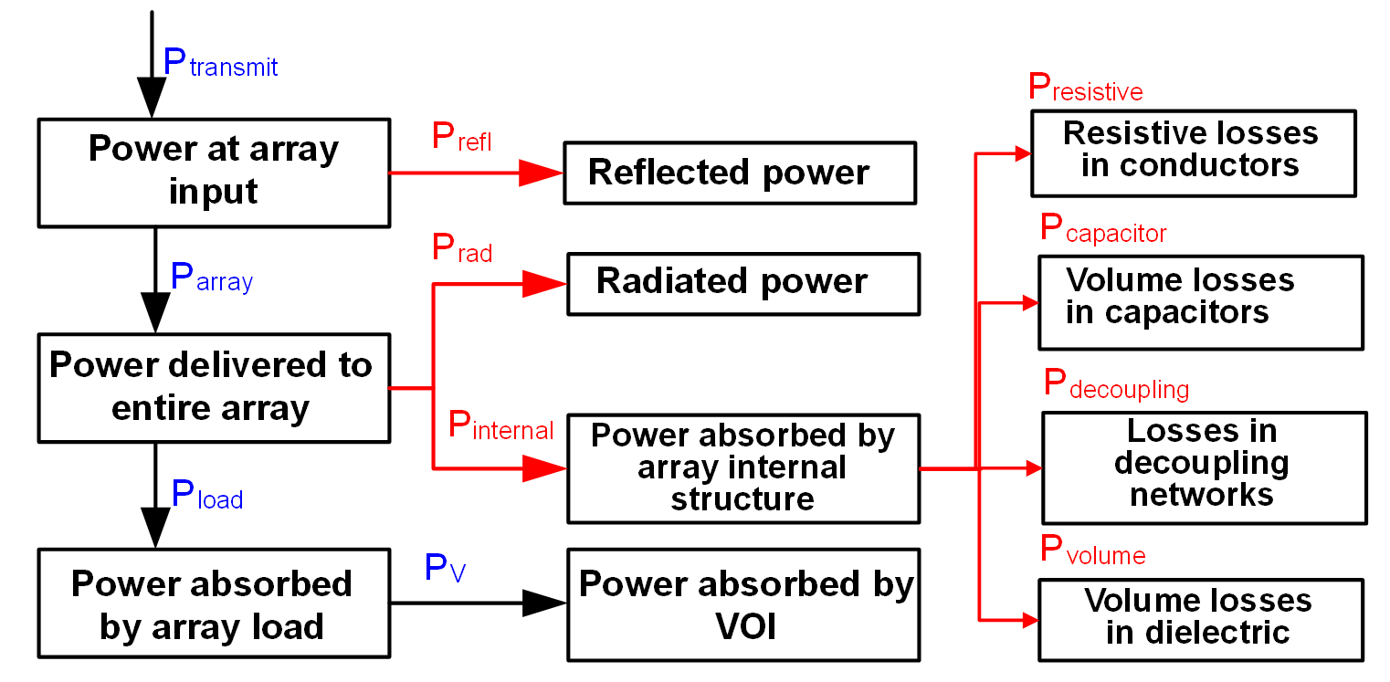
Compliance with laws: Especially for RF safety assessment the simulations should fulfill the law of conservation of energy. The easy check is to calculate the power budget (Fig. 1). Use of “ideal” current sources for MRI coil excitation, an approach which enables quick 3-D EM simulation, generally results in miscalculation of the interactions between the radiative elements, and between the radiative elements and the coil load. In most cases it also prevents calculation of the array power budget.
Results convergence: The major limitation of most available commercial tools is the unavailability of built-in methods to validate the numerical model of the MRI array loaded by a human model, and to assess result uncertainty. The uncertainty depends on a) mesh definitions for array radiative element and human model, b) the solver setup: solver stop criteria, time step, etc., c) the model geometry: what parts of MRI scanner are included in the numerical domain, and truncation of the domain. One should distinguish between solver stop criteria for a given simulation iteration (simulation pass) and adaptive solution convergence for a given model simulation, which requires at least two simulations, for example iterations with different mesh resolution, to obtain estimation of convergence for a given quantity. Accumulated knowledge and experience of simulation can be used to improve the speed and reliability of numerical simulation and simulation data analysis.
SAR10g calculation definitions: Calculation procedures of SAR averaged over any 10 g of tissue of the body and over a specified time (SAR10g) should be consistent with the IEEE C95.3 [7] and IEC 62704-1 [8]. Use of calculation procedures developed in-house that have not been validated, with varying definitions for SAR averaging, makes it impossible to compare the values of SAR10g reported by different research groups, and dilutes the “Safety First” criteria that should be respected by the MRI community. There are several queries regarding SAR10g calculation definitions: for example, how a 10 gram cube is defined. All complaints should be addressed to the IEC 106 technical committee that is responsible for development and maintenance of the standard. Only when this standard is updated one can use a “better” or “more scientific looking” procedure for SAR assessment.
Results comparison: A data comparison based solely on magnetic field data may not be sufficient to properly characterize an RF exposure system, especially for safety aspect dominated by electrical field. A computational model can be defined as a good representation of reality if the numerical results are able to replicate the physical scenario within the combined experimental and computational uncertainty.
Reverse engineering: A variety of coil designs is used in commercial MRI systems. For example, each manufacturer varies the exact coil geometry (e.g., coil diameter, coil length, widths of rings and rungs), the properties of electrical components (e.g., capacitor values, capacitor losses), the exact conditions of the RF coil excitation (e.g., feed position, feed phase orientation) to achieve the desired field behavior. These design details are rarely shared publicly as they are considered proprietary information by scanner manufacturers. Tolerances of electrical components for in-house build coils can be substantial. Reverse engineering process allows one to obtain a match between electromagnetic field generated by a given MRI coil taking into account different degrees of freedom. Some of them, for example, lumped element losses are seldom used but they can substantially influence on the electromagnetic field.
Acknowledgements
No acknowledgement found.References
[1] IEC 60601-2-33:2010, Medical electrical equipment - Part 2-33: Particular requirements for the basic safety and essential performance of magnetic resonance equipment for medical diagnosis. International Electrotechnical Commission. www.iec.ch.
[2] G. Shajan, M. Kozlov, J.Hoffmann, R.Turner, K.Scheffler and R.Pohmann. A 16-channel dual-row transmit array in combination with a 31-element receive array for human brain imaging at 9.4T. Magn Reson Med 2014; 71:870-879.
[3] Technical specification ISO/TS 10974, “Assessment of the safety of magnetic resonance imaging for patients with an active implantable medical device”, 1st edition 2012.
[4] ASTM F2182-11a, Standard Test Method for Measurement of Radio Frequency Induced Heating On or Near Passive Implants During Magnetic Resonance Imaging, ASTM International, West Conshohocken, PA, 2011, www.astm.org.
[5] M. Kozlov, R. Turner, "Fast MRI coil analysis based on 3-D electromagnetic and RF circuit co-simulation," J. Magn. Reson., vol. 200, pp. 147-152, Sep. 2009.
[6] M. Kozlov, R. Turner, "Engineering of 7T transmit multi-row arrays," Proceedings of 34th Annual International Conference of the IEEE EMBS, San Diego, California USA, pp. 1089-1092, September, 2012.
[7] IEEE STANDARD C95.3-2002 - IEEE Recommended Practice for Measurements and Computations of Radio Frequency Electromagnetic Fields With Respect to Human Exposure to Such Fields, 100 kHz-300 GHz. www.ieee.org.
[8] P62704-1 - IEC/IEEE Draft International Standard for Determining the Peak Spatial Average Specific Absorption Rate (SAR) in the Human Body from Wireless Communications Devices, 30 MHz - 6 GHz. Part 1: General Requirements for using the Finite Difference Time Domain (FDTD) Method for SAR Calculations. www.ieee.org.
Figures