RF Transmit: Power Delivery, Decoupling, & Duty Cycle
1Radiology, Case Western Reserve University, Cleveland, OH, United States
Synopsis
The RF transmit chain is one of several “black box” systems in the MRI scanner. The implementation of the RF transmit chain has remained fairly consistent since the earliest clinical MRI scanners. The advent of parallel transmission (pTX) provides a compelling opportunity to rethink not only the design of the RF power amplifiers (RFPAs) and coils, but of the entire MRI scanner. In this lecture we will review fundamental RFPA concepts such as linearity and efficiency. We will then explore advanced topics relating to pTX, including control, decoupling, local amplifiers, and switchmode amplifiers.
Introduction
Modern NMR and MRI experiments make use of pulsed RF magnetic fields, referred to as RF pulses, in order to perturb magnetization away from its equilibrium state. These fields are produced by the currents on one or more RF coils surrounding the subject. Depending on the application, subject, and field strength, the peak electrical power delivered to the coils may range up to 35 kW at frequencies up to 300 MHz. Such high power levels require special electronic circuits referred to as RF power amplifiers (RFPAs).RFPA basics
The heart of an RFPA is the active device, which has historically been implemented with vacuum tubes, bipolar junction transistors (BJTs), metal oxide field effect transistors (MOSFETs), and other more exotic technologies. Today most RFPAs in the VHF band (30-300 MHz) make use of MOSFETs (particularly LDMOS FETs) due to their rugged construction and relatively low cost. We will describe how MOSFETs function within typical RFPA circuits and how they must be terminated with appropriate impedances to perform optimally.RFPA classifications
RFPAs may be broadly divided into linear classes (including classes A, AB, B, and C) and switchmode classes (including classes D, E, F and their inverse counterparts). We will cover the various performance characteristics of RFPAs, and discuss the merits of each class[1]–[3]. We will also discuss methods of characterizing and correcting for amplifier distortion and increasing power efficiency [4]–[8].
The linear classes A-C are by far the most common, as they offer good linearity and wide bandwidth with relatively simple construction. However, there is an inherent tradeoff between their linearity and power efficiency. Extracting large amounts of power from a linear RFPA requires the MOSFET to dissipate a comparable amount of power. Extracting this dissipated power from the MOSFET without destroying it requires the use of large heat spreaders and exchangers. Thus power dissipation is thus a key driver in the cost and physical size of the RFPA.
Switchmode amplifiers offer a theoretical efficiency of 100%, (with 90% being a practical result in the VHF band). Switchmode RFPAs achieve high efficiency using resonant filters, and thus their operating bandwidth is relatively limited. Fortunately, MRI applications demand little bandwidth (<100 kHz) from the RFPA. The key disadvantages of switchmode RFPAs for MRI are that they exhibit significant nonlinearities, and require more complex methods of modulating output power.
Linear RFPA resources
We will also look at example RFPA implementations, and discuss means of developing RFPAs for MRI applications. We will emphasize the use of reference designs specified for nearby frequency bands, with components and documentation available from trusted manufacturers and designers [9]–[12].
The MRI transmit chain
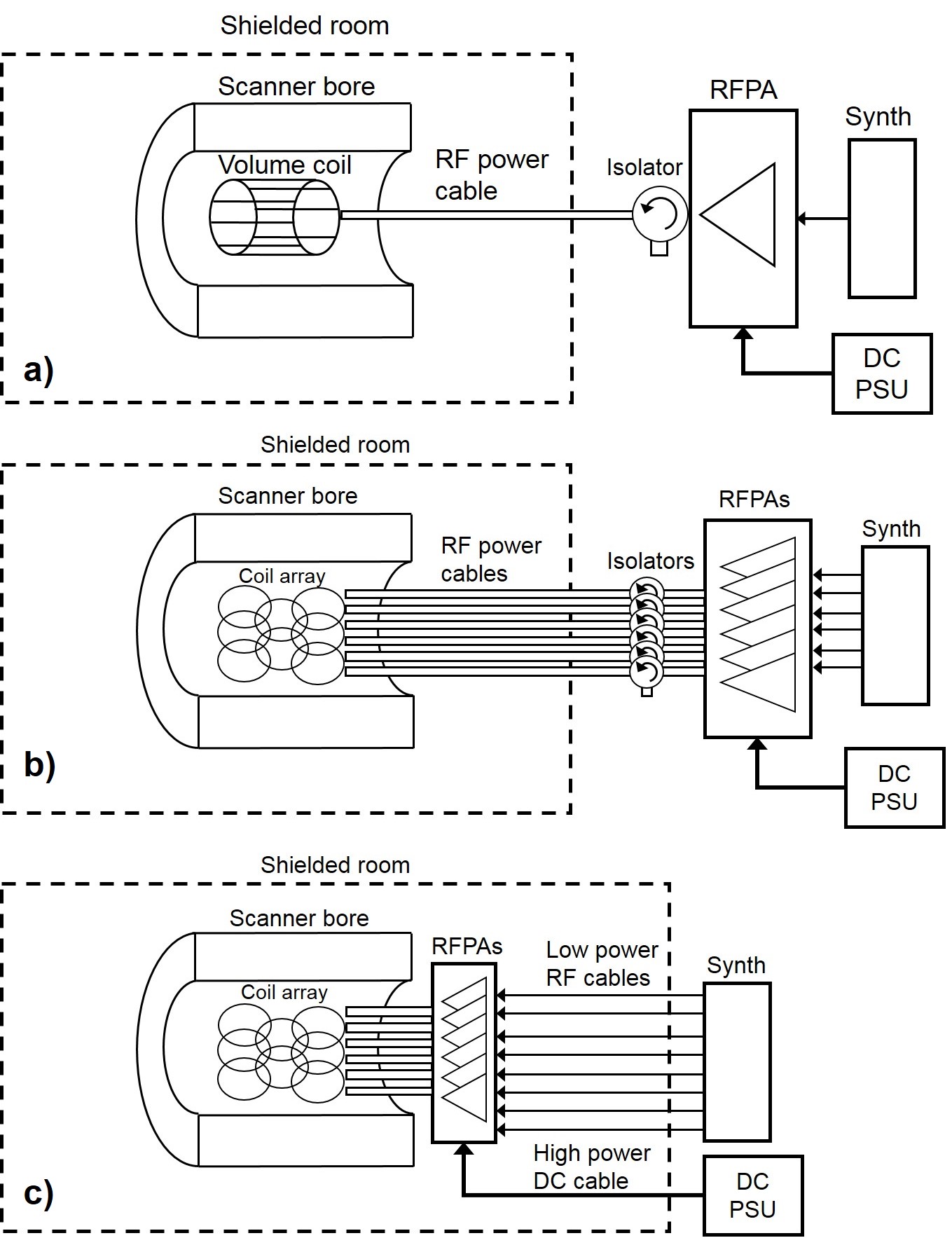
The standard MRI transmit chain uses a single volume coil driven by one high power RFPA as shown in figure 1a. To produce a single RF output with tens of kW of output power, many smaller (e.g. <2kW) RFPAs are combined into a single assembly using power splitters and combiners. The RFPA normally operates in class AB or class C. The combined output of the RFPA is typically connected to a combination of isolators and/or direction couplers which serve as protection against varying load conditions which might damage the RFPA.
Various parts of the RFPA assembly, including the MOSFETs, matching networks, isolator, and cooling systems, may be made of ferromagnetic materials, and therefore the RFPA must be located some distance away from the MRI scanner itself. The RFPA output is coupled to the scanner’s transmit coil via a long, high power RF cable.
The pTX MRI transmit chain
Parallel Transmit (pTX) has been proposed as a solutions to B1+ inhomogeneity[13]–[15] and SAR[16]–[19] in high field MRI. In a parallel transmit system, the standard volume coil is replaced with an array of surface coils, each being driven by an independent RFPA. To produce independent outputs, each RFPA is controlled by a separate RF synthesizer output. Figure 1b shows a block diagram of a typical pTX signal chain.
The use of multiple RFPAs in a pTX setup brings up new engineering challenges as well. Ideally, the current on each RF coil should be independent of the current on other coils, but mutual impedance between coil elements will cause channels to “couple” to each other. This has the effect of making the spatial B1+ profile of each channel less unique, but this can be corrected if the coupling matrix of the array is known, or by using closed loop feedback[4], [20], [21]. We will discuss prior work using RFPAs with mismatched output impedances to implement amplifier decoupling in much the same way low input impedance LNAs are commonly used to mitigate coupling in receiver arrays[22]–[25]. Another negative effect is that RF power coupled from one array port to another is effectively wasted, further decreasing the overall power efficiency of the array. This wasted power cannot be mitigated with predistortion or amplifier decoupling.
Emerging pTX systems
A second major challenge associated with pTX systems is RF cabling. In a single-channel system a large, low loss power cable is used, which keeps transmission losses low. As channel count increases, cables must become thinner in order to fit in a limited space. Thinner cables will have higher attenuation, and therefore more powerful RFPAs will be necessary to compensate. It has been suggested cable losses be mitigated by locating the RFPAs inside or adjacent to the MRI bore, as shown in figure 1c. Doing so requires that the RFPAs be compatible with the static magnetic field B0, and that they not excessively heat the patient or cryostat. We will explore methods of meeting these demands using novel RFPA and array designs[26]–[28].Conclusions
The RF transmit chain is one of several “black box” systems in the MRI scanner. The implementation of the RF transmit chain has remained fairly consistent since the earliest clinical MRI scanners. The advent of parallel transmission provides a compelling opportunity to rethink not only the design of the RFPAs and coils, but of the entire MRI scanner. However, for this to happen, the “black box” aspects must be demystified.Acknowledgements
I would like to thank the faculty, staff, and students of the Case Center for Imaging Research.References
[1] P. Reynaert and M. Steyaert, RF Power Amplifiers for Mobile Communications. Springer, 2010.
[2] M. Kazimierczuk, RF power amplifiers. Chichester, West Sussex, U.K: Wiley, 2008.
[3] K. H. Billings and T. Morey, Switchmode power supply handbook, 3rd ed. New York: McGraw-Hill Professional, 2011.
[4] D. I. Hoult, G. Kolansky, D. Kripiakevich, and S. B. King, “The NMR multi-transmit phased array: a Cartesian feedback approach,” JMR, vol. 171, no. 1, pp. 64–70, Nov. 2004.
[5] P. P. Stang, A. Kerr, W. Grissom, J. M. Pauly, and G. C. Scott, “Vector Iterative Pre-Distortion: An Auto-calibration Method for Transmit Arrays,” presented at the 17th annual ISMRM, Honolulu HI, 2009.
[6] K. Zhu et al., “RF Amplifier Nonlinearity Correction for Multiband RF Pulses,” presented at the 23rd annual ISMRM, Toronto CA, 2015.
[7] W. A. Grissom, A. B. Kerr, P. Stang, G. C. Scott, and J. M. Pauly, “Minimum Envelope Roughness Pulse Design for Reduced Amplifier Distortion in Parallel Excitation,” MRM, vol. 64, no. 5, pp. 1432–1439, Nov. 2010.
[8] P. Stang, J. M. Pauly, and G. C. Scott, “A High-Efficiency Linear MRI Transmit Amplifier Using Envelope-Tracking,” presented at the 20th annual ISMRM, Melbourne AU, 2012.
[9] R. Frey, “A 128 MHz Pulse Amplifier Using the ARF475FL RF MOSFET.” Microsemi Inc Power Products Group, Dec-2009.
[10] “Communication Concepts, Inc.” [Online]. Available: http://communication-concepts.com/.
[11] “Amateur Radio Station W6PQL.” [Online]. Available: http://www.w6pql.com/.
[12] S. Taheri, P. Stang, J. Pauly, and G. C. Scott, “Explorations of Non-Magnetic Amplifiers for MRI Applications,” presented at the 24th annual ISMRM, Singapore, 2016.
[13] P. Van de Moortele et al., “B1 destructive interferences and spatial phase patterns at 7 T with a head transceiver array coil,” MRM, vol. 54, no. 6, pp. 1503–1518, Dec. 2005.
[14] A. G. Webb and C. M. Collins, “Parallel transmit and receive technology in high-field magnetic resonance neuroimaging,” Int. J. Imaging Syst. Technol., vol. 20, no. 1, pp. 2–13, Mar. 2010.
[15] L. Wald, “RF Field Transmission: B1 Field Non-Uniformity, & SAR,” presented at the 22nd annual ISMRM, Milan IT, 2014.
[16] H. Homann et al., “Local SAR management by RF shimming: a simulation study with multiple human body models,” MAGMA, vol. 25, no. 3, pp. 193–204, Jun. 2012.
[17] N. Gudino et al., “Parallel transmit excitation at 1.5 T based on the minimization of a driving function for device heating,” presented at the 21st annual ISMRM, Salt Lake City UT, 2013.
[18] C. McElcheran, L. Golestanirad, and S. Graham, “Reduced Heating of Implanted Electrical Conductors Using Parallel Radiofrequency Transmission,” presented at the 22nd annual ISMRM, Milan IT, 2014.
[19] B. Guérin et al., “Comparison of simulated parallel transmit body arrays at 3 T using excitation uniformity, global SAR, local SAR, and power efficiency metrics: Comparison of simulated parallel transmit 3 T body arrays,” MRM, vol. 73, no. 3, pp. 1137–1150, Mar. 2015.
[20] M. G. Zanchi, P. Stang, A. Kerr, J. M. Pauly, and G. C. Scott, “Frequency-Offset Cartesian Feedback for MRI Power Amplifier Linearization,” IEEE TMI, vol. 30, no. 2, pp. 512–522, Feb. 2011.
[21] N. Gudino, J. A. Heilman, M. J. Riffe, O. Heid, M. Vester, and M. A. Griswold, “On-coil multiple channel transmit system based on class-D amplification and pre-amplification with current amplitude feedback,” MRM, vol. 70, no. 1, pp. 276–289, Jul. 2013.
[22] P. B. Roemer, W. A. Edelstein, C. E. Hayes, S. P. Souza, and O. M. Mueller, “The NMR phased array,” MRM, vol. 16, no. 2, pp. 192–225, Nov. 1990.
[23] K. N. Kurpad, S. M. Wright, and E. B. Boskamp, “RF current element design for independent control of current amplitude and phase in transmit phased arrays,” CMR, vol. 29B, no. 2, pp. 75–83, Apr. 2006.
[24] X. Chu, X. Yang, Y. Liu, J. Sabate, and Y. Zhu, “Ultra-low output impedance RF power amplifier for parallel excitation,” MRM, vol. 61, no. 4, pp. 952–961, Apr. 2009.
[25] M. Twieg and M. A. Griswold, “Optimizing the Current-Mode Class D (CMCD) Amplifier for Decoupling in pTX Arrays,” presented at the 23rd annual ISMRM, Toronto CA, 2015.
[26] L. DelaBarre, D. Myer, and J. T. Vaughan, “Muti-Channel, In-Bore Power Amplifiers for Multi-Channel Coil at 7T,” presented at the 21st annual ISMRM, Salt Lake City UT, 2013.
[27] K. N. Kurpad, E. B. Boskamp, and S. M. Wright, “Eight channel transmit array volume coil using on-coil radiofrequency current sources,” Quantitative Imaging in Medicine and Surgery, vol. 4, no. 2, pp. 71–78, Apr. 2014.
[28] M. Twieg and M. A. Griswold, “High efficiency radiofrequency power amplifier module for parallel transmit arrays at 3 Tesla: High Efficiency in-Bore RFPA Module for pTX at 3T,” MRM, Oct. 2016.
Figures