Magnets: Design, Manufacturing, Installation, Present & Future Technology
Synopsis
The field of an MRI magnet is generated by a circulating current through a sectioned superconducting coil, kept at its operating temperature by a refrigerated cryostat. Active shielding coils confine the stray field to a small volume near the magnet. This presentation covers various aspects of design and operation of these magnets.
Introduction
The function of an MRI magnet is to generate a strong, temporally stable and spatially homogeneous magnetic field over the field of view of the scanner. It has to do this in a reliable, safe and cost effective way, requiring minimal user interaction and with minimal magnetic impact on the surrounding hospital space. Of the many existing technologies and topologies available to perform this function, the cylindrical superconducting magnet has become the most popular and this class of magnets will be the focus of this lecture.
Today’s MRI magnets are pure electromagnets; the field is generated by current flowing in wire and except for some field correction, they do not contain significant amounts of iron to shape or enhance the field. For each tesla of central field one needs approximately 10 000 turns at a current of 300 amperes (what actually counts is the product of the two numbers, the ampere-turns number). Typical current densities in an MRI magnet are of the order of 200 A/mm2. Densely packing so much current in such a small volume is only feasible if this current does not dissipate power. This dictates the use of superconductors. State of the art MRI magnets use an alloy of Niobium and Titanium (NbTi) as the superconducting material; this must be cooled to approximately 4K, the temperature of liquid helium, to operate.
Elements of a superconducting MRI magnet
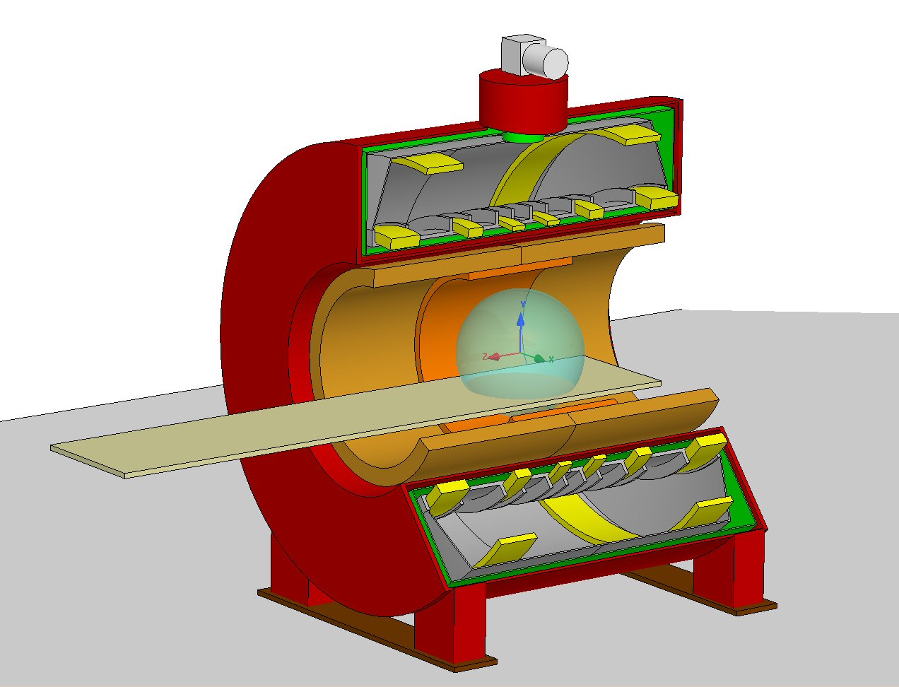
The main components of an MRI magnet are shown schematically in figure 1. The magnet consists of:
- The superconducting circuit. The magnet windings are usually grouped in sections with a rectangular cross-section. All sections are connected in series, with some additional components needed to energize, stabilize and protect the magnet.
- Structural parts to hold the coils in position and to react the magnetic forces.
- A heat exchange and thermal buffer system (usually a tank with liquid helium in which the coils are at least partially immersed). In some designs, the coil support and the helium tank are integrated structures.
- An outer vacuum container, creating a high-vacuum insulation between the cold mass (items 1-3) and the outside world. This is the part you look at when you see an MRI magnet in a hospital.
- A refrigerator, consisting of a so-called cold head on the magnet and a compressor in the technical room. State of the art refrigerators can extract up to 1.5 watt from the helium tank and ensure zero helium boil-off if the total heat load on the cold mass stays below this cooling capacity.
- A thermally conducting radiation shield, intercepting radiation heat from the room temperature wall. This shield is connected to the first stage of the refrigerator, which can typically absorb 50 watt. The shield is usually made from aluminium and its temperature is between 40 and 60 kelvin.
- A multi-layer insulation blanket (many layers of thin reflective foil) mostly located outside of the radiation shield reduces the radiation heat load of the shield to what the refrigerator can cool away.
- A cold mass support system, usually consisting of high-strength low conductivity fibers holds the inner parts of the magnet stably in position.
- An access and vent tube connecting the helium tank with the outside world.
Magnetic design
All MRI magnets have circular symmetry about the cylinder-axis of the system. The central field is directed along this so-called z-axis. If the magnet windings would form a simple long solenoid with uniform turns density, the field would only be uniform if the coil were of infinite length. If the coil is truncated, the field on the axis drops off with the square of the distance to the center of the magnet. This field drop-off can, to some extent, be compensated by adding turns at the ends. Such designs have indeed been built, in particular for 7 tesla and higher, but such systems are generally quite long, which is bad for patient comfort and ease of siting.
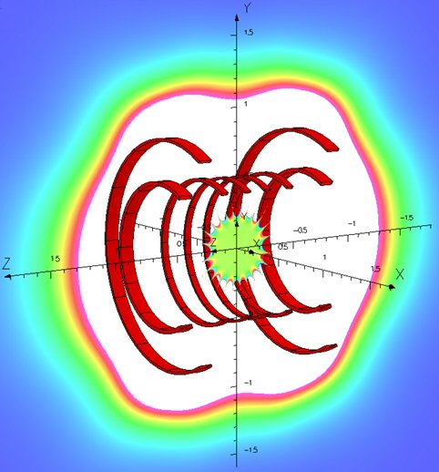
Far more compact designs with better homogeneity can be achieved by cutting up the solenoid into shorter sections with voids in between. Practical MRI magnets built today consist of 4-8 field generating sections, with a length to diameter ratio of 1.3-1.6. Here the field on axis drops off with the 10th or 12th power of the distance to the midplane. Moving away from the center in other directions, the field increases or decreases in a complex pattern (mathematically a high-degree spherical harmonic function), as shown in figure 2. The shark-bite behavior of the field at the boundary of the imaging volume is an inherent property of the design and it cannot be changed significantly by shimming.
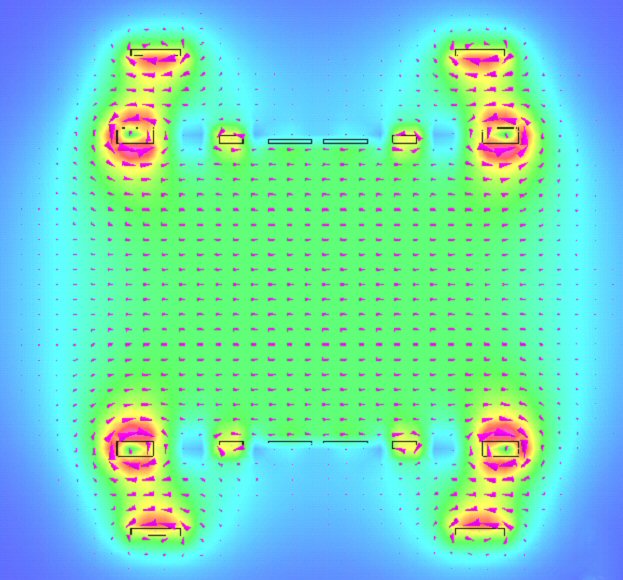
One of the consequences of sectioning the magnet is that regions of high field appear on the inner boundaries of the coil sections, as shown in figure 3. The maximum field seen by turns in the end coils of typical 3 tesla magnets can be as high as 6 tesla. As the critical current of a superconductor goes down with increasing field, this high peak field reduces the magnet's margin or, alternatively, this margin has to be bought back by using a conductor with a higher critical current.
The magnet of figure 2 also features two coil sections at a larger diameter. These are the active stray-field compensation coils, in which the current flows in the opposite direction. Their diameter and number of turns is selected such that the net magnetic dipole moment of the magnet becomes close to zero (the dipole moment of a coil section is equal to the number of ampere-turns multiplied with the area enclosed by the section). Nulling the dipole moment makes the far field of the magnet behave like a quadrupole, where the field falls off with the inverse fifth power of the distance. The active shielding sections generate a field of approximately 1/3 of the central field in the wrong direction. Therefore the amount of wire in an actively shielded magnet is significantly greater than in an unshielded magnet of the same strength.
In order to achieve the designed
field homogeneity, the manufacturing process has to ensure that all windings
are positioned with an accuracy of the order of 0.1 mm (taking into account the
effects of cooldown shrinkage and elastic deformation due to magnetic and other
forces). The residual inhomogeneity (typically < 1000 ppm) can be shimmed
out nearly perfectly. After a ramp cycle the coils have to move back to the same position as where they were before within a few micron, otherwise the magnet needs to be re-shimmed.
Forces and stresses
Within a coil section, the individual turns attract each other magnetically and generate a compressive stress in the winding bundle. In order to prevent wire motion due to this stress, the windings are, in most MRI magnet designs, held firmly together by impregnating the coil during or after winding with a bonding material (ranging from wax to glass-reinforced epoxy resin). In addition to the internal forces, there are also large net forces between coil sections. In general, the magnet wants to get shorter in length and larger in diameter. The axial force in the midplane of a 3T magnet is of the order of 3000 kN (mostly caused by the end-sections of the magnet). The radially directed force on the shield windings causes an average hoop stress of the order of 100 MPa, which is close to the yield stress of a superconducting wire.
The magnetic forces and stresses generally increase with the square of the central field of the magnet. One of the major challenges in superconducting magnet design is the reaction of these large electro-magnetic forces against the mechanical support structures. Relative motion at any of these interfaces will likely generate enough frictional heat that it heats up the coil above the critical temperature of the wire; the start of a quench.
Magnet stored energy, quench
A 3T MRI magnet typically has an inductance of 100 H for a magnet current of 400 A. The magnetic stored energy of this inductor is 0.5 L I^2, which yields 8 megajoule. At constant shape, the magnetic energy increases with the square of the central field.
If, for whatever reason, a small section of the superconductor becomes resistive, the dissipation at this point will heat up itself and adjacent windings. If the size of the resistive region exceeds the so called minimal propagating zone (which is quite small), the process is irreversible and the normal zone quickly spreads through the entire coil section. This process, called a quench, will not stop until the current in the magnet has decayed to zero, thereby converting all of the magnetic energy of the magnet into heat. Because this heat is going to be dumped in the cold mass anyway, it is best to spread it over as large a volume of magnet material as possible, to avoid local hot-spots. This is done by firing auxiliary quench heaters in coil sections that are still superconducting, after an initial quench has been detected. Typically it takes 2-5 seconds for the current (and the field) to decay to zero. After this, the heat in the coils is gradually transferred to the helium, which is then blown off over a much longer time. The emergency shutdown system of an MRI magnet is a set of heaters in the coil, driven by an external power supply, which initiate a quench. Magnets are designed to survive a quench without permanent damage. Usually there will be at least some liquid helium left in the magnet after a quench.
Persistent mode operation, response to external fields
In normal operation, the superconducting coils are all connected in series and form a closed loop. The total resistance seen by the current in this loop is of the order of 1 nanoOhm. This resistance will cause a dissipation of less than a microwatt, which is deducted from the ~10 MJ of magnetic energy in the system. This ratio of dissipation to stored energy determines the field drift rate, which is usually well below 0.1 ppm/hr. In order to change the current in the magnet, the superconducting circuit has to be temporarily interrupted. For this purpose, the magnet comprises a so-called persistent mode switch, a piece of superconducting wire with a heater. Activating the heater causes the resistance of this part of the superconducting circuit to increase to 10-100 ohm, which is enough to ramp the magnet current up or down. Closed superconducting circuits counteract externally applied field changes: if an external source causes a net flux change in the closed loop, the circulating current changes such that the net flux change is zero. At first sight one would expect that MRI magnets would thus be inherently insensitive to external field changes. If the magnet is actively shielded, this is not the case, because an external source would cause almost zero flux change in the magnet. It takes additional superconducting circuitry, either a separate closed loop or superconducting shunts inside the magnet circuit, to achieve the desired immunity against fields from moving elevators or trains.From factory test to hospital operation
MRI magnets are usually cooled down only once in their lifetime, as the first step of the factory testing. After ramping the magnet to field for the first time, it is checked that it can deliver a stable and uniform field and that its cryogenic performance is within specification. The magnet is then shipped to its final destination, cold and full of helium. If the refrigerator is not running, the helium will last for a transit time of 1-2 weeks.
After hospital installation, which involves final shimming to compensate for magnetic effects of the environment, the magnet is left untouched as long as the gradual field drift allows. Depending on the tuning range of the RF subsystems, the field has to be topped up about once every 1-2 years.
If the cryocooler is working properly no helium should escape from the system. Nevertheless, it is useful to monitor the helium level at regular intervals to catch problems early. If helium is lost this can be due to a reduction in cooling power, but helium loss can also be caused by a small leak, for example at the seal of the filling port.
Emerging new magnet technologies
Today’s zero boil-off magnet technology, combined with helium saving measures under transport and service conditions are a first step to reduce MRI’s dependence on the availability of liquid helium.
Technologies to completely eliminate helium and where the magnet is actively refrigerated without an intermediate helium bath are in development in many places. One approach is to retain the conventional NbTi superconductor, to be operated around 4 kelvin. This requires an efficient way to transfer the heat from the coil sections to the refrigerator(s). Apart from this heat transfer problem, a major issue is how to deal with conditions where the heat load on the cold mass exceeds the refrigeration power. Examples of such transient conditions are refrigerator outage, ramping the magnet or heavy scanning where gradient-induced losses are higher than what the cryocooler can handle. The heat capacity of all materials (except helium) near 4K is so small that a small imbalance between heat input and cooling power will quickly lead to a quench.
Another approach to a magnet without a liquid helium bath is to use a superconductor with a higher critical temperature. Examples of such materials are Magnesium Diboride (MgB2) and Niobium Tin (Nb3Sn). Still higher temperature superconductors (e.g. 2G YBCO) are also being investigated for application in MRI magnets, but their cost is still prohibitively high.
Acknowledgements
No acknowledgement found.References
- Wilson, M. N. Superconducting magnets. (Clarendon, Oxford, 1983).
- Cosmus, T. C. & Parizh, M. Advances in whole-body MRI magnets. IEEE Trans. Appl. Supercond. 21, 2104–2109 (2011).
- Lvovsky, Y., Stautner, E. W. & Zhang, T. Novel technologies and configurations of superconducting magnets for MRI. Supercond. Sci. Technol. 26, 093001 (2013).
- Razeti, M. et al. Construction and operation of cryogen free MgB2 magnets for open MRI systems. IEEE Trans. Appl. Supercond. 18, 882–886 (2008).
Figures