Spin Echo Imaging
1MR Applications & Workflow, GE Healthcare, Menlo Park, United States
Synopsis
The spin echo pulse sequence is one of the most important pulse sequences in MRI. Fast spin echo imaging is routinely used due to its robustness to susceptibility variations and local field inhomogeneities, as well as for its ability to produce excellent T1, T2 and PD images. The aim of this lecture is to describe the basic physical principles governing spin echo imaging and to illustrate the effect of key imaging parameters, such as TE, TR and ETL (echo train length) on image contrast.
Aim:
The aim of this lecture is to illustrate the basic physics underlying spin echo (SE) and fast spin echo (FSE) imaging. Physical principles will be explained in simple terms, favoring intuition over mathematical formulations, and several examples, from common clinical applications will be presented to directly illustrate the effect of changing important imaging parameters, such as TE, TR and ETL (echo train length) on image quality, image contrast and scan time.Specific objectives:
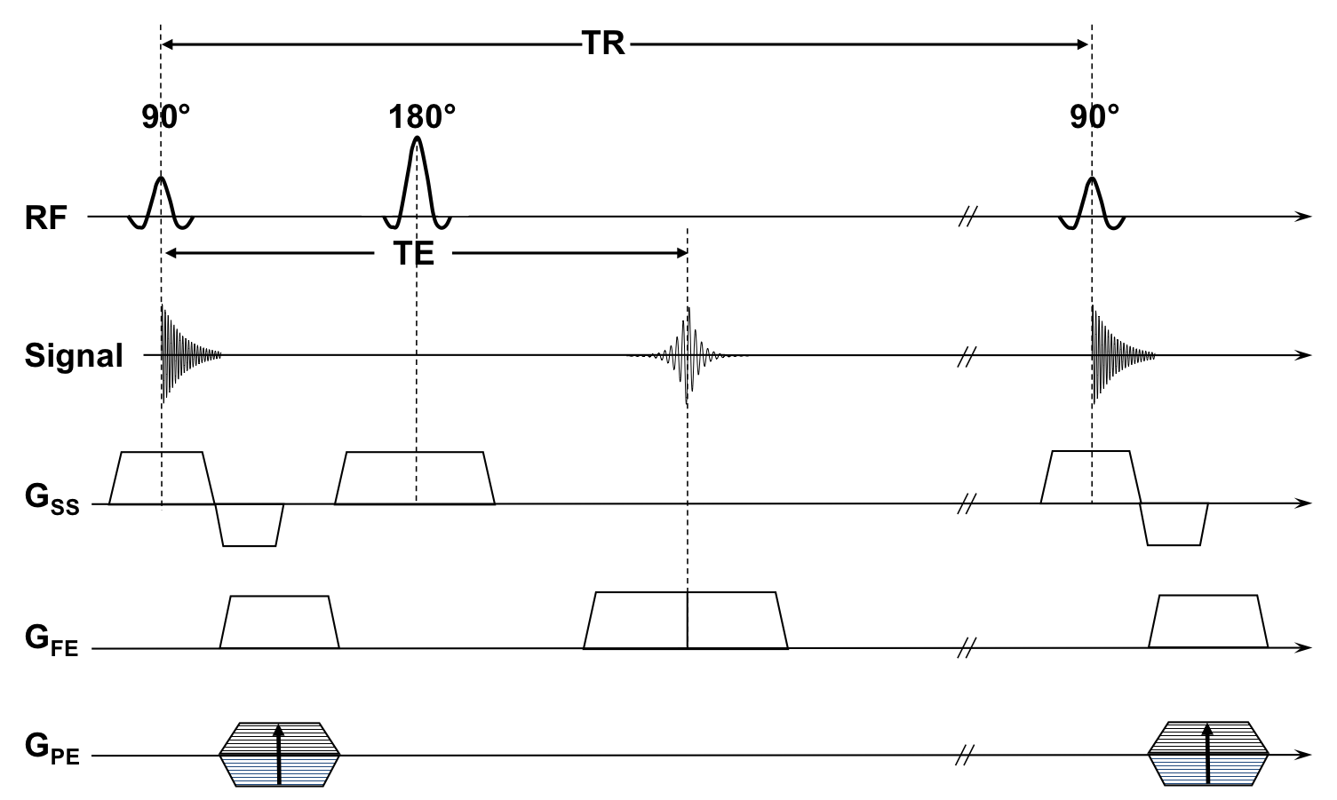
- Understand how spin echoes are formed and how they can be used to generate different image contrasts. SE pulse sequences always start with a 90 degrees excitation pulse that tips the magnetization in the transverse plane. Static magnetic field inhomogeneities cause spins to dephase, resulting in the transverse magnetization to decay with time constant T2*. A 180 degree RF pulse applied at time TE/2, where TE is the desired echo time, effectively reverses this dephasing process due to static magnetic field inhomogeneities, until all the spins will come back into phase at t=TE, when a spin echo is formed. It’s important to understand that while the dephasing due to static magnetic field inhomogeneities is rephased at the time of the spin echo, the effect of non-static field inhomogeneities due to spin-spin interactions are not rephased, which results in T2 weighting of the detected signal. Figure 1 shows a simple spin echo pulse sequence.
- Understand strengths and pitfalls of SE-based pulse sequences and how they compare to gradient-echo-based techniques. From the simple description above follows that SE pulse sequences are insensitive to magnetic field inhomogeneities. This is one of the definite advantages of SE imaging. However, several spin echoes are necessary to form an image as each echo corresponds to a single line in k-space and the pulse sequence in Figure 1 needs to be repeated for each phase encoding step. Depending on the desired contrast, a relatively long time might be needed for the longitudinal magnetization to recover (according to T1 relaxation) before the next SE experiment can start. This is why SE acquisitions, unlike gradient-echo-based ones, tend to be quite long. Other important differences between SE- and gradient-echo imaging, including flow-related effects, RF energy deposition and TE/TRs achievable with each technique, will be discussed during this lecture.
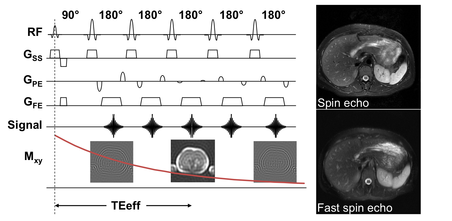
- Understand the basic physics underlying fast spin echo imaging and some of the most common clinical applications. In a Fast Spin Echo (FSE) pulse sequence, the excitation pulse is followed by a train of refocusing pulses, so that multiple spin echoes are generated. Each echo is phase encoded differently, so that several lines of k-space are acquired following each excitation pulse, significantly reducing scan time. FSE, also known as Turbo Spin Echo (TSE) or RARE (Rapid Acquisition with Relaxation Enhancement), is one of the most commonly used pulse sequences, because of its robustness to susceptibility variations and field inhomogeneities, as well as for the diverse image contrasts that can be generated. Figure 2 shows a simplified FSE pulse sequence with ETL=5. Note that in this case the effective echo time (Teff) is defined as the time when the center of k-space, which contains most of the energy, is acquired.
- Learn to recognize common artifacts encountered in fast spin echo imaging and simple mitigation strategies to improve image quality. FSE imaging techniques have replaced conventional SE protocols in many applications, due to the shorter duration of the acquisition. However, long echo trains also mean increased blurring due to T2-induced decay along the echo train and increased RF power deposition. Figure 2 shows the typical blurring encountered in long-echo-train FSE with respect to SE imaging. Differences in contrast between SE and FSE due to magnetization transfer effects and other mechanisms will be briefly discussed.
Summary:
By the end of this lecture, participants should understand the basic physical principles underlying SE imaging. In particular, they should appreciate the role played by different imaging parameters to obtain the desired image contrast as well as to mitigate common artifacts encountered in SE and FSE imaging.Acknowledgements
No acknowledgement found.References
[1] Jung BA , Weigel M, Spin echo magnetic resonance imaging. JMRI 2013, 37:805-817. This is a brief, excellent review of the material that will be covered during this lecture.
[2] Haacke EM,Brown RW,Thompson MR,Venkatesan R, Magnetic resonance imaging: physical principles and sequence design. New York: John Wiley and Sons; 1999. Classical book on MRI physics.
Figures