5560
Of Active Catheters and Guidewires: How do Guidewires affect the Tracking Signal Intensity?1Dept. of Radiology, Medical Physics, Medical Center - University of Freiburg, Freiburg, Germany, 2Department of Cardiology and Angiology I, University Heart Center, Freiburg, Germany, 3MaRVis, Frechen, Germany
Synopsis
Active tracking or profiling coils mounted on catheters provide high signal. Other devices in the vicinity can alter the signal acquired by the catheters. The effects of guidewires on the signal from actively tracked catheters were investigated in phantom and in vivo. A standard metallic guidewire and a MR safe guidewire with a passive marker were introduced through the catheter and tested for different positions at the tip. The signal loss was substantial for both guidewires. When the metallic guidewire passed through the catheter tip, the signal was unstable, whereas the MR safe guidewire did not cause any distortions.
Introduction
The lack of ionizing radiation, cross-sectional imaging and functional measurements are advantages of MRI over X-ray imaging, which have led to an increased interest in MR-guided catheterization as an alternative to fluoroscopy. A fundamental problem of MR-compatible catheters is their inherent lack of MR signal, which can be overcome using active tracking or profiling coils mounted to the device1. These tracking coils can lead to unwanted heating, and they can be difficult to integrate; however, they facilitate the detection of the catheter in tortuous vessel geometries. In this work we investigate the interaction between guidewires and actively tracked catheters, focusing on the change in signal intensity of the active tracking coil in proximity to guidewires.Methods
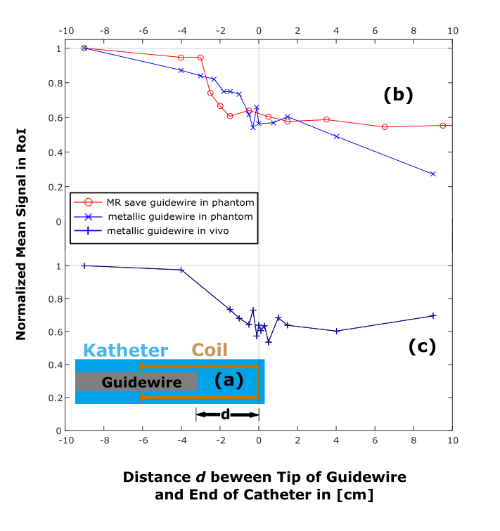
An active profiling catheter for coronary artery interventions was constructed from a commercial 5F tiger shaped catheter (Optitorque, Terumo Europe E.V., Leuven, Belgium). A loop coil was attached to the catheter tip, which was connected to one receive channel of a 3T MR system (Magnetom PRISMA, Siemens Healthcare, Erlangen, Germany) via a matching and tuning circuit (coil layout shown in Fig.1(a)). The coil was placed near the catheter tip at a safe distance of 6 cm to the proximal catheter shaft which is reinforced with a metallic braiding for increased steerability, and which causes signal voids in MR images. The interaction of the catheter with two guidewires were investigated: A commercial metallic 0.018’’ guidewire (Radifocus Guide Wire M, Terumo Europe E.V., Leuven, Belgium), and a wire equipped with an MR safe non-metallic guidewire comprising iron microparticles as MR markers in its centric portion along the full length of it, with an additional slightly stronger and broader tip marker at the very distal end of the guidewire (MaRVis MR guidewire, MaRVis, Frechen, Germany).
Guidewires were carefully advanced through the catheter and the tip coil, and for each guidewire position (see Fig1 (a)) several images were acquired (N = 5 for phantom, and N = 3 in vivo) using a real time sequence (trueFISP: TR=673ms, TE=1.6ms, TA=1.6s base resolution: 192x192). Measurements were performed in a phantom and a swine study where the acquisition was ECG triggered. In the experiments all other imaging coils were turned off, and the mean signal intensity at the tip was plotted as a function of the guidewire position.
Results
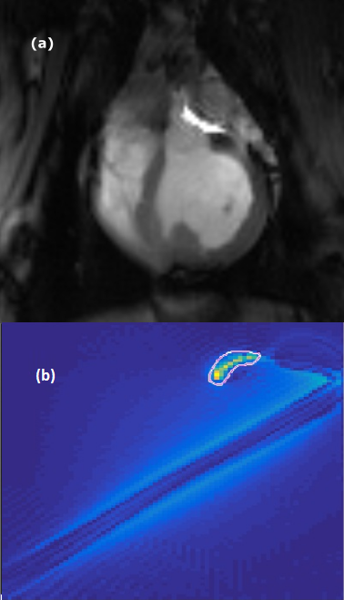
The position of the region of interest (ROI) near the catheter tip (Fig.2(b)) had to be adjusted to account for the changes in position and orientation of the catheter. In Fig.1(b,c) the average signal of the catheter coil is shown for different distances of the guidewire to the catheter tip. The catheter signal decreases upon transit of the guidewire by approximately a factor of two. Fig.2 shows images acquired during the phantom and pig experiments for the metallic guidewire.
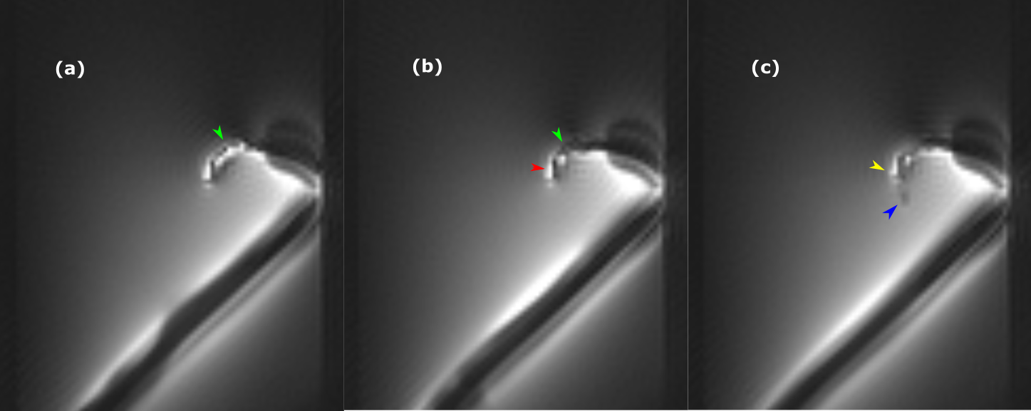
The effect of the MR safe guidewire on the MR signal of the tip coil is shown in Fig.3. As the guidewire enters the loop coil, a localized signal reduction is observed that is caused by the ferromagnetic particles which create signal dephasing in close proximity to the marker only. As the B1 field of the loop coil at the catheter tip extends beyond catheter2, the dephasing effects stay local and the signal is not completely canceled (Fig.3(c)), which allows assessing the current guidewire tip position with very high precision.
Discussion
The results show that guidewires have a substantial effect on the signal intensity in active tracking coils, which varies with the configuration of the guidewire. Nevertheless, the active coil was clearly visible even with the guidewire being fully inserted, and the signal decrease was comparable both in the phantom and in vivo experiments. The signal in case of the marked guidewire reached a plateau after the tip marker left the catheter, while the signal deviation was more volatile in case of the metallic guidewire, which might be caused by the changes of the electrical properties inside the coil for each position of the wire.
In the future, the effect on other coil configurations will be investigated (e.g., solenoid coils), where the signal reduction is expected to be larger, since the guidewire will be pass through the most sensitive region of the coil. The signal void of the MR-compatible guidewire with iron-oxide markers can be useful in catheterization procedures, as the transit of the guidewire tip can be detected via the signal change in the profiling coil.
Acknowledgements
We thank Roland Galmbacher for his help during the animal experiments.
Grant support by the Deutsche Forschungsgemeinschaft (DFG) under grant number BO 3025/2-2 is gratefully acknowledged.
References
1. Bock M, Wacker F; “MR-guided intravascular interventions: Techniques and applications”, JMRI 2008;27(2):326–338
2. Wang et al.: “Real-Time Active MR-Tracking of Metallic Stylets in MR-Guided Radiation Therapy”, MRM 2015;73:1803-181
Figures