5557
Hydrostatically Actuated MRI-Compatible Motion Platform for Dynamic MRI Research1Radiological Sciences, University of California Los Angeles, Los Angeles, CA, United States, 2Biomedical Physics, University of California Los Angeles, Los Angeles, CA, United States, 3Mechanical and Aerospace Engineering, University of California Los Angeles, Los Angeles, CA, United States, 4Bioengineering, University of California Los Angeles, Los Angeles, CA, United States
Synopsis
Motion is one of the main challenges in MRI, including interventional MRI. While many dynamic imaging and motion compensation techniques have been created, comparisons and validation are difficult, since it is difficult to reproduce in vivo motion for multiple experiments. This work proposes the design and development of a 1 Degree-of-Freedom hydrostatically actuated MRI-compatible motion platform, which can reliably reproduce programmed motion for dynamic MRI experiments.
Introduction
Motion is one of the main challenges in MRI, including interventional MRI. While many dynamic imaging and motion compensation techniques have been created, comparisons and validation are difficult, since it is difficult to reproduce in vivo motion for multiple experiments1. Also, it is difficult to controllably test a wide range of motion states in human subjects. This work proposes the design and development of a hydrostatically actuated2 MRI-compatible motion platform, which can reliably reproduce programmed motion for dynamic MRI experiments.Methods
Motion Platform Design:
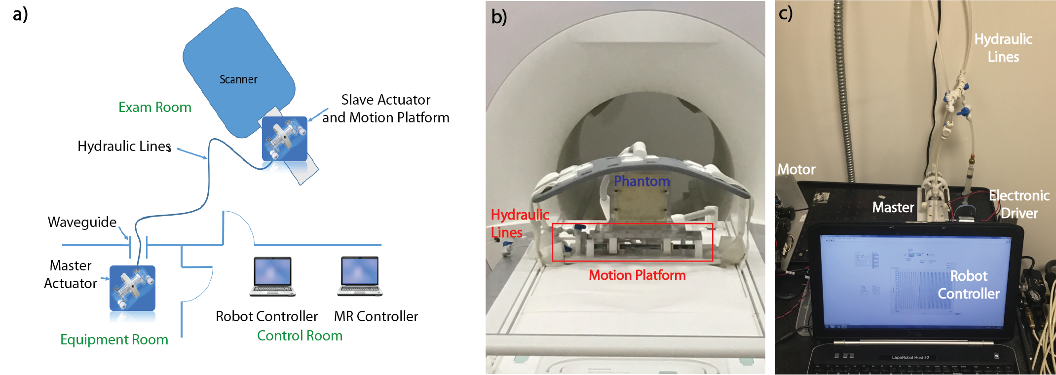
Physical Design: A pair of MRI-compatible master/slave hydrostatic actuators is used to control the 1 degree-of-freedom (DOF) motion of an acrylic platform (Fig. 1). The platform is attached to the slave actuator and is connected to the master actuator via fluid lines that pass through the wave guide of the scanner room. The master actuator is driven by a motor and can be programmed to generate desired motion at the slave actuator and platform.
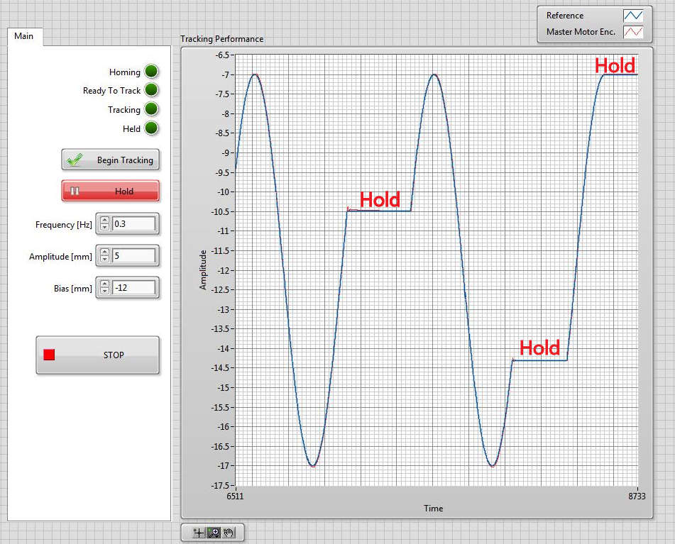
Software Design: The motion platform and its electronics are controlled by software in Labview (National Instruments, USA) (Fig 2). As a representative example, the platform was programmed to undergo reproducible sinusoidal motion that emulates respiratory waveforms. The software allows the user to adjust the frequency and amplitude of the sine waveform in real-time. A “hold” button suspends the motion of the platform until it is pressed again, simulating breath hold commands.
Bench-top Motion Verification: The displacement of the motion platform with different sinusoidal waveforms was measured using laser doppler displacement meters with a resolution of 0.635 micron and compared to the input waveform. The sinusoidal waveforms all had a displacement range of 10mm peak-to-peak, but varied from a frequency of 0.1Hz to 0.6Hz. The system was then tested to see what maximum frequency and displacement range can be obtained without failure.
Imaging Assessment: The motion platform was placed in a 3T MRI scanner (Prisma, Siemens) next to a sphere phantom covered by a body array. Gradient echo (GRE) scans (TE/TR=3.82/105ms, FOV=192x280mm2, Resolution=1.1x1.1x2mm3, FA=10o) of the phantom without the motion platform, with the motion platform while it was powered off, and with the motion platform while it was in motion were acquired. The images were then inspected for artifacts and the signal-to-noise ratio (SNR) was calculated using the two-scan difference method3. The process was repeated with a grid phantom, where dimensions of the imaged grid lines were measured to assess distortion.
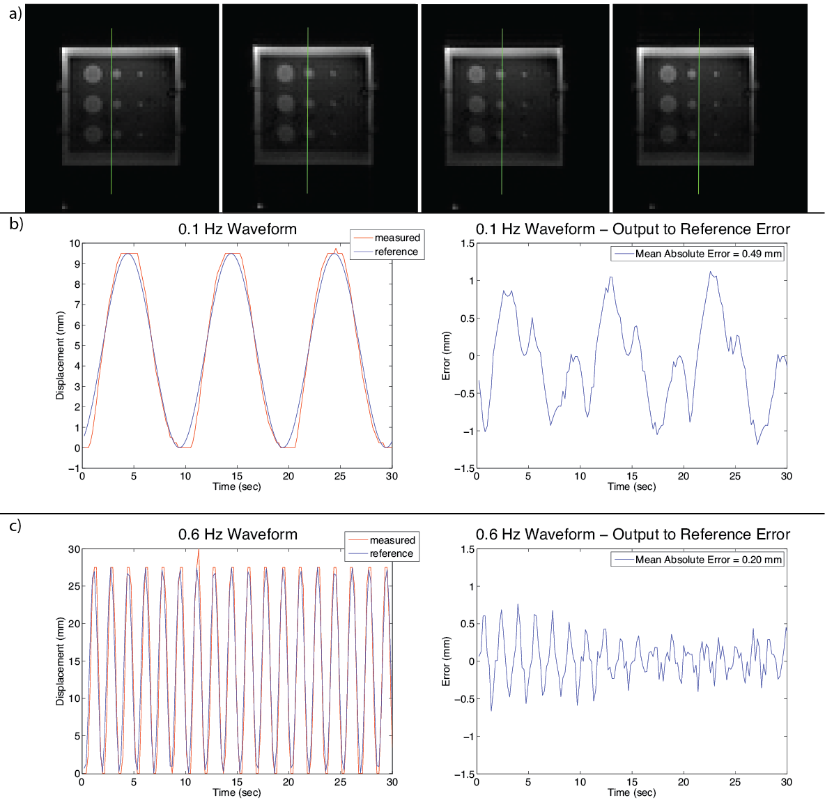
In Bore Motion Verification:
A gelatin phantom was placed on the platform and
the motion platform was programed to move in a sinusoidal pattern, with a
frequency of 0.1Hz and displacement range of 10 mm peak-to-peak. A motion-tracking
algorithm4 was performed on real-time MR images (198ms/frame, spatial resolution = 3.1x3.1x10mm3) of the phantom
and the measured waveform was compared to the input waveform. Next, the
frequency and displacement range were increased up to 0.6Hz and 25mm
peak-to-peak and the analysis was repeated. These frequencies and displacement
ranges were selected because they reflect in vivo respiration.
Results
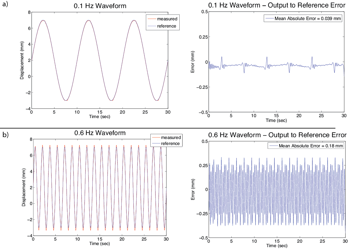
Bench-top Motion Verification: The reference input waveform versus measured motion of the platform can be seen in Figure 3. There is good correlation between the two for a low frequency (0.1 Hz) and higher frequency (0.6Hz) case. The mean absolute error between the measured and the reference waveform for the 0.1Hz case was 0.04mm and for the 0.6Hz was 0.18mm. We observed that the motion platform can reach a maximum frequency of 1.5Hz and a maximum displacement range of 50mm peak-to-peak.
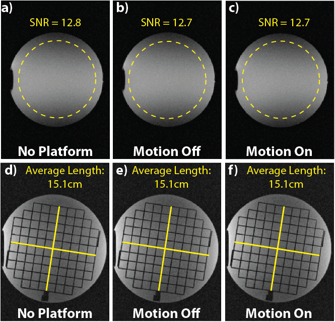
Imaging Assessment: No images artifacts were observed with the motion platform inside the bore. The SNR between the platform on and off is on average only 2.58%. The SNR between the platform in the scanner bore and removed is 2.22% (Fig 4). The grid phantom images showed no distortion.
In Bore Motion Tracking: The measured waveform showed good correlation to
the input waveform in terms of amplitude and frequency (Fig 5). The mean absolute error between the measured and the
reference waveform was 0.50mm for the 0.1Hz case and 0.20mm for the 0.6Hz case.
Discussion and Conclusion
Our hydrostatically actuated motion platform exhibits negligible impact on MR image fidelity and SNR. The actuators generate reproducible motion waveforms consistent with the programmed input signal. This new motion platform can potentially serve as a motion reference for dynamic MRI research. Further work will extend this to additional DOF of motion to replicate a wider range of in vivo motion.Acknowledgements
This project was supported in part by an NSF Graduate Research FellowshipReferences
1. Nofiele J, Yuan Q, Kazem M, Tatebe K, Torres Q, Sawant A, Pedrosa I, Chopra R. An MRI-compatible platform for one-dimensional motion management studies in MRI. Magn. Reson. Med. 2016;712:702–712. doi: 10.1002/mrm.25903.
2. Mikaiel S, Simonelli J, Lu D, Sung K, Tsao T-C, Wu HH. Real-Time MRI-Guided Interventions using Rolling-Diaphragm Hydrostatic Actuators. In: ISMRM 24th Annual Meeting. ; 2016. p. 3588.
3. Dietrich O, Raya JG, Reeder SB, Reiser MF, Schoenberg SO. Measurement of signal-to-noise ratios in MR images: influence of multichannel coils, parallel imaging, and reconstruction filters. J. Magn. Reson. Imaging [Internet] 2007;26:375–85. doi: 10.1002/jmri.20969.
4. Wu HH, Gurney PT, Hu BS, Nishimura DG, McConnell M V. Free-breathing multiphase whole-heart coronary MR angiography using image-based navigators and three-dimensional cones imaging. Magn. Reson. Med. [Internet] 2013;69:1083–93. doi: 10.1002/mrm.24346.
Figures