5463
Loopoles vs. conventional MR loops under safety considerationsJörg Felder1, Chang-Hoon Choi1, and N. Jon Shah1,2
1Institute of Neuroscience and Medicine (INM-4), Forschungszentrum Jülich, Jülich, Germany, 2Faculty of Medicine, Department of Neurology, JARA, RWTH Aachen University, Aachen, Germany
Synopsis
While the application of loopole configurations may be beneficial to improve B1 distribution at high fields it comes with the drawback of reduced voltage withstanding capability during transmission. This either implies use with lower transmit power or the addition of more capacitors which in turn degrades the quality factor of the coil and thus efficiency and sensitivity of the antenna element.
Purpose
Recently “loopoles” – loops using a spatially asymmetrical distribution of capacitance1,2 – have been proposed to improve SNR and B1 homogeneity at high field strengths. In the transmit case, the improvements in B1 distribution have to be balanced against quality factor degradation. As capacitance becomes unequally distributed, voltage drops across the capacitors of the coil also distribute unequally and require a higher number of elements in order to withstand the driving voltage.Methods
One standard loop and two loopole configurations were investigated for voltage withstanding capacity and temperature rise when the antenna is driven using an MRI RF power amplifier (PA). All antennae were constructed from copper tape (13 mm wide) glued onto a polycarbonate substrate and consisted of a quadratic loop of 100 mm x 100 mm. One loop was constructed as a standard loop antenna used in MRI with equally distributed capacitors and their capacitance around its circumference. The second loop had capacitors placed in the same locations as the first but the capacitance was unequally distributed. The third loop had matching and feeding capacitors at the coil terminal while the remaining capacitors were placed on the opposite side of the feeding point. All setups used type C capacitors (ATC Corp., NY, USA). We first measured S-parameters and Q values of the three arrangements when loaded with a 1-litre water phantom doped with 1.24g NiSO4 + 2.62g NaCl using a standard vector network analyser (ZNB, Rohde & Schwarz, Germany). In a second step the coils were connected to the PA of a 3T Tim a Trio System (Siemens Healthcare AG, Erlangen Germany) and RF pulses with a duty cycle of 5% were applied. The power was stepped up until sparking on the coils appeared. During a 5 min experiment and pulsing with 250 W, temperature on the coils was monitored using an infrared camera system (FLIR Systems Inc. Oregon, USA).Results
All three loop configurations could be tuned and matched well with the phantom load as shown in Fig. 1. Q-factors of these coils are similar. When driven with 5 ms rectangular pulses of 250 W power and a repetition rate of 100 ms, the temperature distribution shown in Fig. 2 was obtained. The first configuration with equal distribution of capacitance stayed below 30ºC – while the local temperature in the other two configurations rose to 41ºC and 35ºC, respectively. This clearly indicates higher local power dissipation in the smaller valued capacitors in these cases and comes close to the maximal permissible surface temperature of applied parts according to IEC 60601. The finding was confirmed when increasing excitation power to 500 W where the second and third antenna started arcing across the capacitors. In contrast the conventional loop configuration could be driven with up to 2 kW transmit power without arcing.Discussion
While there might be benefits in B1 distribution in loopole configurations compared against standard MRI loops using an spatially equal distribution of capacitance these come at the cost of greatly reduced voltage withstanding capacitance. This, in turn, requires the use of serial capacitors to split the voltage drop in multiple parts and the associated reduction in coil quality factor. Thus the gain in field distribution must be balanced against a loss in efficiency and sensitivity of the loopole configuration. The coil designer should be aware of this trade-off and must establish the optimum configuration for the designated application.Acknowledgements
No acknowledgement found.References
1. Ha S, Zhu H, Petropoulos L. Asymmetrically segmented loop phased coil for uniform RF field excitation at 7T. Proc. ISMRM. 2015;3117.
2. Lakshmanan K, Brown R, Wiggins GC. A 3D loop-loopole receive array for spine imaging at 3.0T. Proc. ISMRM. 2016;171.
Figures
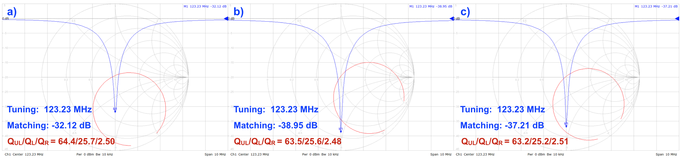
Figure 1: S-parameters of all three coils including
Q-factors acquired using a network analyzer
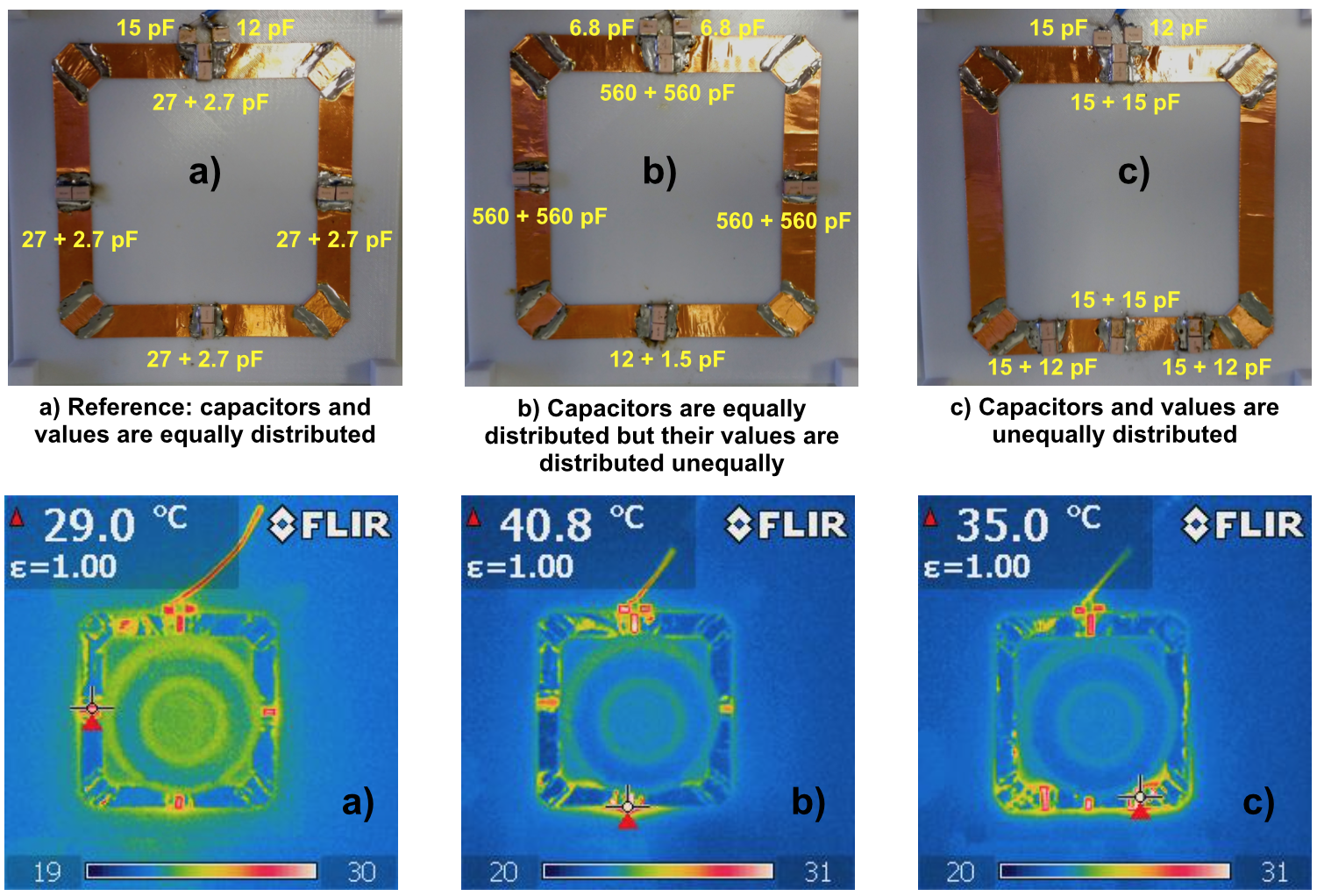
Figure 2: Coil pictures with component values and
corresponding temperature maps