5456
Safety of MRI on patients with abandoned/retained cardiac leads: Patient-derived simulation studies at 64MHz and 127MHz1Massachusetts General Hospital, Charlestown, MA, United States, 2Radiology, Northwestern University, Chicago, IL, United States, 3Medicine, Northwestern University, 4Radiology, Massachusetts General Hospital, Charlestown, MA, United States, 5Life Science Engineering, Mittelhessen University of Applied Sciences (THM), Giessen, Germany
Synopsis
Despite the tremendous effort to develop MRI safety protocols to reduce complications in patients with cardiac implantable electronic devices with intact leads, almost nothing is known about the variation and extent of RF heating in patients with fractured or abandoned leads. Here we report the preliminary results of the first systematic simulation study of RF-induced SAR amplification at and around abandoned cardiac leads in patients undergoing MRI at 1.5 T and 3.0 T with different imaging landmarks.
Introduction
There is a steady growth in the use of cardiac implantable electronic devices (CIED) worldwide. There are more than 3 million patients with permanent pacemakers in the US [1] and the number grows by 80,000 annually [2]. It is estimated that 50%–75% of patients with CIED may need to undergo MRI over their lifetime for non-cardiac or cardiac indications [3], with many patients requiring repeated examinations [4]. In a sizeable fraction of patients endocardial leads fail for technical reasons, aging, or patient growth, and the patient is being referred for lead extraction [5]. However, the physician is not always able to perform a complete extraction and may need to abandon the lead [6]. Despite the tremendous effort to develop MRI safety protocols to reduce complications in patients with intact CIEDs [1, 2, 7], almost nothing is known about the variation and extent of RF heating in patients with fractured or abandoned leads. Currently, due to a lack of information on potential safety hazards scanning of patients with retained leads is considered an absolute contraindication for MRI. Here we report the preliminary results of the first systematic simulation study of RF-induced SAR amplification around abandoned cardiac leads in patients undergoing MRI at 1.5 T and 3 T.Methods
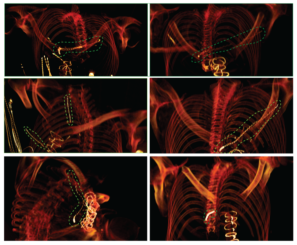
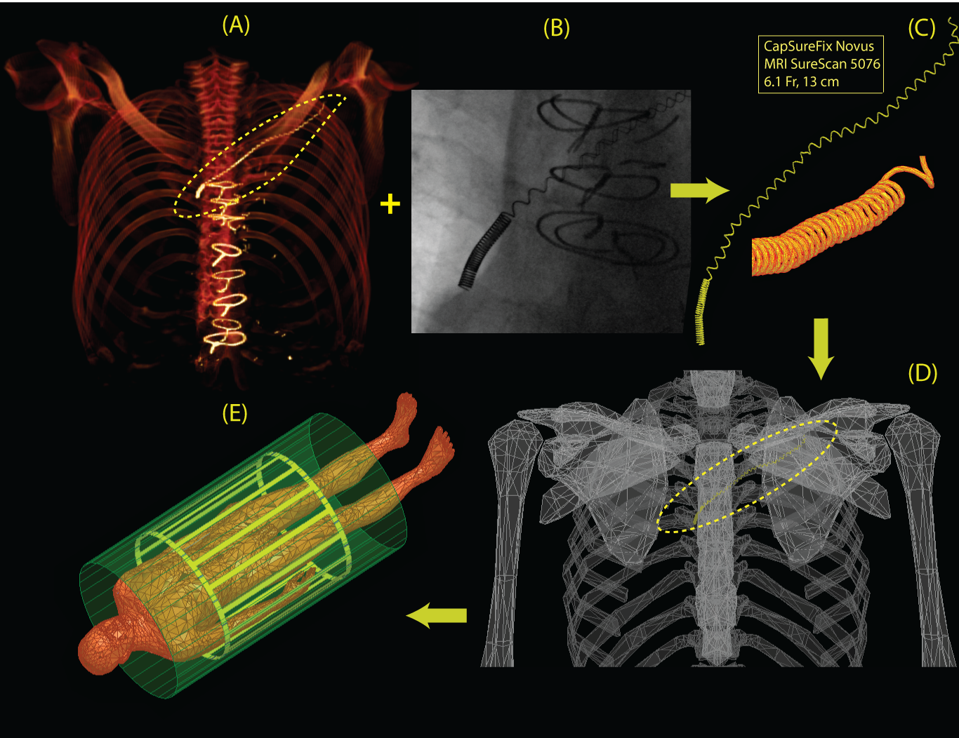
Patient identification and model construction: Twenty-five patients with history of implanted cardiac devices and retained leads who had chest CT/ MRI/ X-ray images between August 2006 and August 2016 were identified through a query of the enterprise data warehouse at Northwestern Memorial Hospital. CT images were manually segmented to extract the 3D trajectory of the abandoned leads as well as the silhouette of patient’s torso (Fig.2A). Details of leads’ structure including number of spiral turns and variations in the pitch were partially extracted from X-ray images (Fig.2B), and partially from manufacturer’s datasheet. Models were constructed and processed using commercially available image segmentation and 3D surface construction tools. Lead models were exported to ANSYS Electronics Desktop 16.2 (ANSYS, Canonsburg, PA, USA) and registered to ANSYS human body model for FEM simulations.
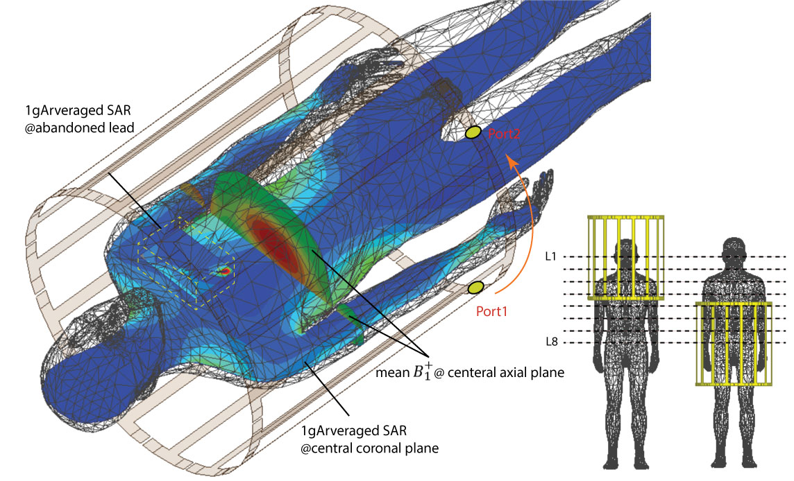
MRI RF coils: Specific models of high-pass birdcage body coils (diameter 610mm, length 670mm) with quadrature excitation were built and tuned in ANSYS HFSS at both 64 MHz (1.5 T) and 127 MHz (3 T). For each lead model, simulations were performed with body coils operated at 8 different imaging landmarks separated by 10 cm, covering an area from head to the abdomen. At each imaging landmark, coils were rotated around the patient’s body to account for different feed-body positions (Fig.3).
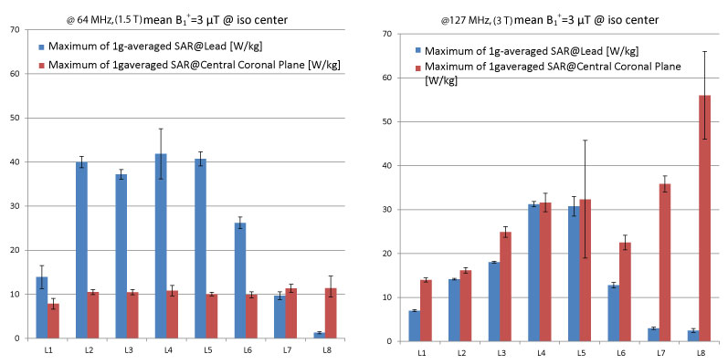
SAR and B1+ calculations: The spatial mean of B1+ field was calculated on an axial plane passing through coils’ iso-center. At each feed position and at each imaging landmark, the input power for each coils was adjusted to produce a mean B1+=3µT on the central axial plane. 1g-averaged SAR was calculated inside a cubic region encompassing the lead. 1g-averaged SAR was also calculated on a coronal plane passing through the center of the body as a reference for comparison. The maximum of 1g-averaged SAR on the central coronal plane is referred to as reference SAR.
Results
Figure 4 shows the result of the reference SAR and the maximum 1g-averaged SAR at the lead for a representative patient model (averaged over different feed positions). At 3 T, the maximum of 1g-averaged SAR around the lead was always smaller than the reference SAR. At 1.5 T, the maximum of 1g-averaged SAR was less than the reference SAR at imaging landmarks at the level of kidneys toward lower limbs. It is important to note however, that although local SAR values around the lead were higher than the reference SAR at 1.5 T, those SAR values were not significantly higher than the typical local SAR values observed in the tissue at 3 T.Discussion and Future Work
To our knowledge, this work is the first attempt to quantitate local SAR in the tissue around abandoned cardiac leads based on patient-derived realistic models of lead geometries and MRI RF coils. Our results have considerably substantial implications; if verified in larger patient cohorts they may justify the application of 3 T MRI on patients with abandoned leads using conventional clinical imaging protocols. More broadly, quantitative results of the completed study will help designing optimum imaging protocols and determining safe power limits based on specific imaging landmark and RF frequency. This could bring MRI accessible to a sizeable patient population who can significantly benefit from MRI diagnostic power but is currently deprived from its superior benefits.Acknowledgements
This work has been supported by NIH grants K99EB021320 and P41EB015896.References
[1] A. J. Greenspon, J. D. Patel, E. Lau, J. A. Ochoa, D. R. Frisch, R. T. Ho, et al., "Trends in permanent pacemaker implantation in the United States from 1993 to 2009: increasing complexity of patients and procedures," Journal of the American College of Cardiology, vol. 60, pp. 1540-1545, 2012.
[2] T. Sommer, C. P. Naehle, A. Yang, V. Zeijlemaker, M. Hackenbroch, A. Schmiedel, et al., "Strategy for Safe Performance of Extrathoracic Magnetic Resonance Imaging at 1.5 Tesla in the Presence of Cardiac Pacemakers in Non–Pacemaker-Dependent Patients A Prospective Study With 115 Examinations," Circulation, vol. 114, pp. 1285-1292, 2006.
[3] R. Kalin and M. S. Stanton, "Current clinical issues for MRI scanning of pacemaker and defibrillator patients," Pacing and clinical electrophysiology, vol. 28, pp. 326-328, 2005.
[4] C. P. Naehle, V. Zeijlemaker, D. Thomas, C. Meyer, K. Strach, R. Fimmers, et al., "Evaluation of cumulative effects of MR imaging on pacemaker systems at 1.5 Tesla," Pacing and clinical electrophysiology, vol. 32, pp. 1526-1535, 2009.
[5] R. A FRIEDMAN, H. ZANDT, E. Collins, M. LeGras, and J. Perry, "Lead extraction in young patients with and without congenital heart disease using the subclavian approach," Pacing and clinical electrophysiology, vol. 19, pp. 778-783, 1996.
[6] M. S. Silvetti and F. Drago, "Upgrading of VVIR pacemakers with nonfunctional endocardial ventricular leads to VDD pacemakers in adolescents," Pacing and clinical electrophysiology, vol. 29, pp. 691-696, 2006.
Figures