5455
Suitability of right angle pathway for testing RF-induced Spinal Cord Stimulation lead heating in an MRI1Systems Engineering, Nuvectra Medical, Broomfield, CO, United States, 2R&D, Nuvectra Medical, Broomfield, CO, United States, 3R&D, Medical Technology Labs, La Mirada, CA, United States
Synopsis
This work evaluates the suitability of various pathway models to represent the worst-case heating for a Spinal Cord Stimulation lead when subjected to MRI RF-intensive exposure. The ideal model represents relevant pathways that a lead can take between any two points with the fewest variable factors. One model, used for evaluation of safety for Spinal Cord Stimulation (SCS) devices, describes a path with 4 variable factors – IPG starting position (Z), vertical rise of the proximal end of the lead (H1), lateral span width (W), and rise of the distal end of the lead within the central axis (H2). The “right angle” model is evaluated direct diagonal, half-way diagonal, and one in which all vertical rise is confined to the central axis of the MRI.
Purpose
In order to evaluate the MRI RF-induced heating safety of implantable medical devices, a proper pathway model is required. The ideal model represents relevant pathways that conductive leads can take between any two points with the fewest factors. The "right angle model", used for evaluation of safety for Spinal Cord Stimulation (SCS) devices, describes a path with 4 variable factors – IPG starting position (ZPG), vertical rise of the proximal end of the lead (H1), lateral span width (W), and a rise of the distal end of the lead within the central axis (H2).
An advantage of the right angle model (relative to more complicated ones) is that it requires few variables to describe the pathway. Since proof of safety requires evaluation of any potential pathway configuration, experiments are required in order to determine representative worst-cases. The complexity for the design of sensitivity experiments increases exponentially, as the number of pathway variables increases.
The suitability of the right angle model is contingent on how it represents (or brackets) the family of alternative clinically relevant paths between two given points. Intuition suggests that right angle is worst case for SCS because the vertical rise section, H1, occurs in the region with the highest magnitude and most tangential E-field. The purpose for the experiment described herein is to test the proposition that a right-angle lead path always results in greater heating than other more direct lead pathways that could connect the IPG implant to the spinal anchor point within a body phantom.
Methods
The method used to test the right angle model's suitability was to place an SCS stimulation system in a polyacrylic acid (PAA) gel phantom1, under a variety of pathways, and measure lead tip temperatures when exposed to MRI. A comparison of the measured results was analyzed to determine which pathway yielded the highest temperature and the relative differences between them. The SCS system used in the experiment included a 24 channel Nuvectra™ 2408 IPG connected to a 1081-60 lead with 5208 40 cm extension. The lead’s 8 electrodes are spaced 1mm apart.
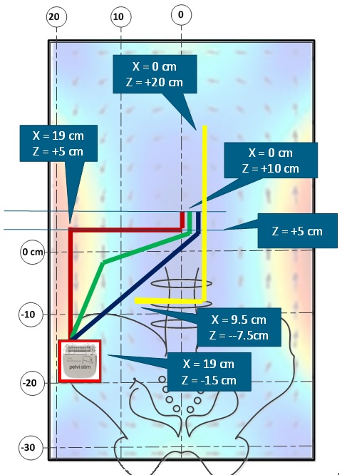
The pathway configurations evaluated include the “right angle”
path, the "half way to diagonal", “direct diagonal”, and vertical only in central axis paths. Each pathway had common IPG and lead tip
locations except for last one. The IPG was located at in an
ASTM body phantom -19 cm left of and -16 cm below the MRI’s isocenter. See Figure 1.
LumaSense fiber optic thermometry probes were placed within 1 mm of the first, fourth, sixth, and eighth electrode of the stimulation lead. A closed bore GE Signa Excite 1.5T was set to 2.77 W/kg whole body average RF-intensive scan for 10-minutes.
Results
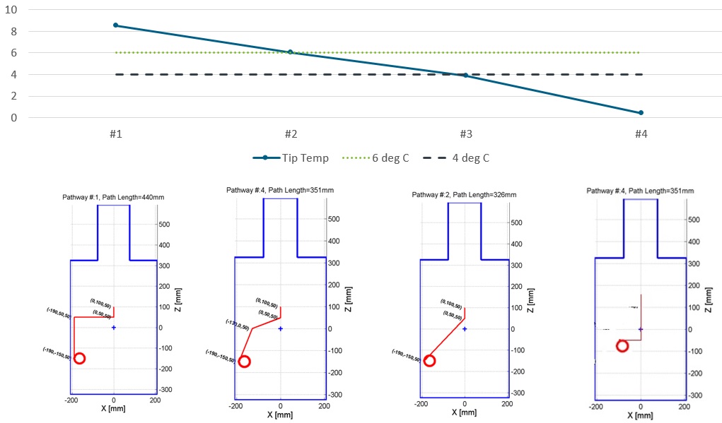
The measured lead tip temperature rise for each pathway configuration are shown graphically in Figure 2. The highest temperature (8.5 °C), as expected, was with the "right angle" pathway. The next highest temp (6.0 °C) occurred with the "half-way to diagonal" pathway. The next was the "diagonal pathway" (3.9°C). And, the lowest temperature (0.4 °C), as expected, was measured using the pathway in which all vertical rise occurred in the central axis.
Discussion
The measured temperature rise with the last case (all vertical rise within the central axis) should be compensated for the extra attenuation due to its longer distal segment as prescribed in Kalpin, et al.2 Applying an inverse attenuation effect for the extra 22 cm of length, the compensated temperature for the last case would be 0.86 °C.Conclusion
Based on the results of the experiment described, "right angle" serves as a suitable pathway model for SCS device RF-induced heating safety testing. Suitability, for safety analysis, is synonymous to yielding a temperature that is greater than equal to the family of pathways that could connect any IPG implant location to the central axis and ultimately the lead tip. For this definition of suitability, the "right angle" yielded a temperature of almost 2x that of the most clinically relevant pathway - the direct diagonal. Clinically, the lead is anchored at the spinal incision point and then tunneled to the IPG implant location in a nearly direct diagonal path. Evaluation of the non-diagonal paths, such as the "half-way to diagonal path", provides for insight on the sensitivity to off-diagonal variation of pathway.
The suitability of the right angle pathway model does not necessarily extend to other neuro-stimulation systems and therapies. Evaluation of the right-angle model, as well as other models, for deep brain, peripheral nerve, and sacral nerve stimulation therapies is a useful future direction.
Acknowledgements
No acknowledgement found.References
1. ASTM F2182–09. Standard test method for measurement of radio frequency induced heating near passive implants during magnetic resonance imaging. West Conshohocken, PA: ASTM International 2009.
2. Kalpin, Scott; Kaula, Norbert; Shehada, Ramez. "Attenuation of RF-induced currents within neuro-stimulation leads using a helical conductor design", Proc. Intl. Soc. Mag. Reson. Med. 24 (2016), pending
Figures