5449
Study of RF coupling and heating in multi-wire SEEG Electrodes.1Physics, Case Western Reserve University, Cleveland, OH, United States, 2Cleveland Clinic Foundation, Cleveland, OH, United States
Synopsis
A SEEG electrode contains a number of contact points and as many number of insulated wires each following a contact. Here, we studied the coupling among the contact wires of SEEG electrode inserted into phantom, by using temperature measurements at different contact points, and varying the lengths of contact wires. From the experiment, we saw that, changing the length of one contact wire will result in change in temperature rise to other contacts also, even if wire lengths corresponding to those contacts are unchanged. This shows significant coupling among the wires at the RF frequency of 3T MRI system.
Purpose
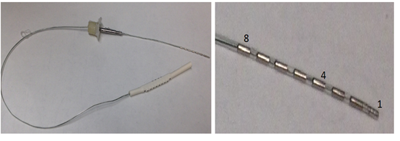
The RF heating from in-situ electrodes during MRI scans is a safety concern, and there have been many published measurements of RF heating near single wire implants, guidewires, and electrodes1-5. However, no measurements have been reported on the impact of RF coupling among the multiple contacts and contact wires in stereoelectroencephalography (SEEG) electrodes used for epilepsy studies. SEEG electrodes, as shown in Figure 1, have multiple sensing surfaces (contacts), and the same number of insulated wires (contact wires) connecting them to readout instrumentation. The wires are insulated from each other, but may couple with each other in addition to coupling with the RF field. The effect of this coupling is studied with measurements of RF heating near SEEG electrodes that are penetrating a phantom. Temperature measurements were performed during a RF transmit sequence in a 3 T MRI system using a head-only, transmit and receive RF coil.Methods
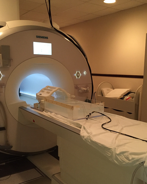
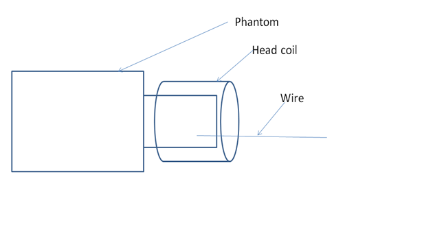
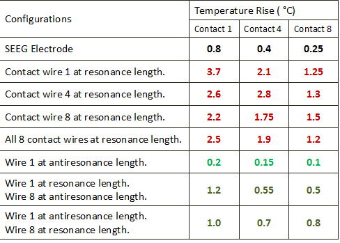
For the experimental measurements, an 8-contact SEEG (model no 2101-08-091, PMT Corporation) electrode is inserted into an ASTM Phantom in filled with gelled saline and instrumented with temperature sensors (model m3300, Luxtron Santa Clara, CA USA). The whole set up is placed inside a 3 T Siemens Prisma MRI system with head Tx/Rx coil as shown in Figure 2. The SEEG has 8 contact points, each connected to its own insulated lead wire (contact wire) and total length of 35 cm between to ends of the electrode. For this experiment, 9 cm of the electrode is inserted straight into the phantom. The SEEG and wire leads are placed parallel to, but offset from, the main axis, and enter the phantom 4 cm below the top and 2 cm inside from the lateral surface. For measurements, different configurations were created by connecting 0.5 mm diameter wire of different lengths to the different ends of the lead wires. This method allowed for measurements where the length of the wire attached to each contact point could be independently controlled. During the RF sequence, the temperature rise was measured at the contact points 1, 4 and 8 (1 is the most distal contact point, 4 is the middle one and 8 is the most proximal one as referenced to the entry point of electrode into phantom) of the electrode by placing the thermal sensors at the respective positions and applying TSE sequence with a head SAR of 2.8 W/Kg, whole body SAR of 0.2 W/Kg, time averaged RF Power of 8.3 W, TR = 6470 ms, TE = 71 ms, Turbo Factor = 15 and Echo trains per slice = 18 (Figure 3 shows Schematic of experiment). To find the maximum heating (resonant) and minimum heating (antiresonant) lengths of the wire, we changed the length of the contact wire 1, keeping other wires at fixed lengths (35 cm the electrode length). The resonant length was found as 65cm and antiresonant length as 125 cm. Then, temperature measurements were made by setting wire lengths at different resonant and antiresonant combinations, as shown in table (Figure 4).Results
The temperature measurements for different configurations are presented in table (Figure 4). The measurements demonstrate the RF coupling among the wires of SEEG electrode. If any one of the wires is extended to the resonant length (65 cm), then the temperature at each of the three contacts is increased, by at least a factor of 3 compared to just the SEEG electrodes alone. Also, adding a wire at the antiresonant length (125 cm) will reduce the maximum temperature rise in all 3, but the temperature may still be higher than the SEEG electrode alone, if there is another wire at the resonant length.Discussions
The results presented in the table (figure 4) indicate that the temperature rise at the particular tip changes on changing other wire lengths, even if the corresponding wire length is constant. So there is significant effect of one contact wire length, on the temperature rise at the contact (tip) of another wire, indicating significant amount of coupling among the wires. The temperature rise is maximum at the contact '1' in almost all cases, because this will act as the real tip due to the coupling effect.Acknowledgements
This research was supported in part by a Fellowship from the Cleveland Clinic Foundation Epilepsy Center.References
1. Young CJ, Karmarkar P, and McVeigh ET. Minimizing RF Heating of Conducting Wires in MRI. Magn Reson Med 2007; 58:1028-1034.
2. Armenean C, Perrin E, Armenean M, Beuf M, Pilleul F, Saint-Jalmes H. RF-induced Temperature Elevation Along Metallic Wires in Clinical Magnetic Resonance Imaging: Influence of Diameter and Length. Magn Reson Med 2004; 52:1200-1206.
3. Konings MK, Bartels LW, Smits HFM, Bakker CJG. Heating Around Intravascular Guidewires by Resonating RF Waves. J Magn Reson Imaging 2000; 12:79-85.
4. Nitz WR, Oppelt A, Renz W, Manke C, Lenhart M, Link J. On the Heating of Linear conductive structures as Guide Wires and Catheters in Interventional MRI. J Magn Reson Imaging 2001; 13:105-114.
5. Carmichael DW, Thornton JS, Rodionov R, Thornton R, McEvoy A, Allen PJ, Lemieux L. Safety of Localizing Epilepsy Monitoring Intracranial Electroencephalograph Electrodes Using MRI: Radiofrequency-Induced Heating. J Magn Reson Imaging 2008; 28:1233-1244.
Figures