5447
Coil losses significantly alter the electromagnetic fields of a 64 MHz quadrature driven birdcage coil1MR:comp GmbH, Gelsenkirchen, Germany, 2Max Planck Institute for Human Cognitive and Brain Sciences, Leipzig, Germany, 3Division of Biomedical Physics, U.S. FDA, CDRH, Office of Science and Engineering Laboratories, Silver Spring, MD, United States
Synopsis
We investigated the dependence of the incident electric field (E) generated in the ASTM phantom on the coil losses. The results showed that magnetic field (H) normalized to √wbSAR, depends on capacitor Q factors. To avoid systematic errors in predicting the induced electric fields inside a human body the coil model should include realistic coil losses. Our results indicate that the use of ratio E to ||H|| at the coil iso-center normalization to predict E inside a human body located in a commercial birdcage coil based on a numerical coil model with arbitrary coil losses can result in high errors.
Introduction
Due to the complexity of assessing RF-induced heating in-vivo, computational modeling has been widely used. To assess RF-induced heating of conductive elongated devices (e.g., leads of medical devices), it is necessary to know the incident tangential electric field (Etan) along the device trajectory. The electric (E) and magnetic (H) fields induced in a patient, or a phantom, depends on the coil geometry (i.e., coil length and diameter, rungs), the electrical circuitry of the feeds, coil excitation, and coil losses. Numerical simulations are often used to compute the Etan, because the measurement of E field is challenging. The effect of coil losses on E and H are often neglected in literature. We herein show the dependence of E and Etan generated in the ASTM phantom1 on the coil losses.Method
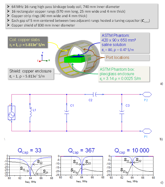
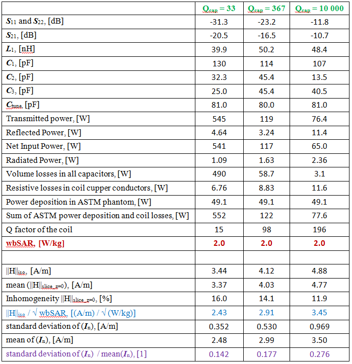
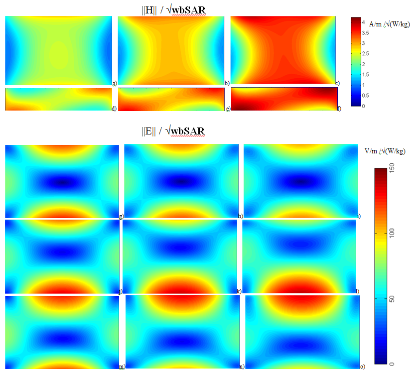
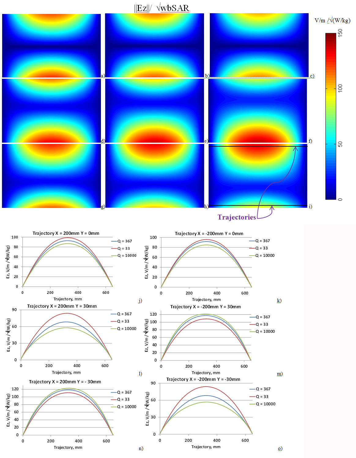
The simulated coil was a 64 MHz 16-rung high pass birdcage body coil (Fig. 1a) based with the dimensions of the Medical Implant Test System (Zurich Med Tech, Switzerland) . Coil losses were modified by applying three different capacitor Q factors (Qcap): 33 (previously used in2), 367 (to mimic a low-quality capacitor), and 10000 (to model nearly lossless capacitors). The RF feed sub-circuit providing impedance matching and decoupling of the two channels was the multi-element circuit shown in Fig. 1b (see3 for additional details). The coil was tuned for the three Qcap cases (Fig. 1c) and driven in quadrature mode. 3D EM simulations were performed with HFSS (ANSYS, Canonsburg, PA, USA). The mesh adaptation procedure with 30% increase of mesh elements was stopped if the variation of ||E||max (maximum of electric field magnitude (||E||) over entire ASTM phantom) between two consecutive meshes was less than 3%. E and H inside the ASTM phantom were obtained on an equidistant mesh of 1 mm. ||E|| and the magnitudes of the z and x components (i.e., ||Ez|| and ||Ex||) were analyzed on three coronal planes (i.e., y={-30,0,30} mm). The values of E and H, as well as the current magnitudes in each rung (In, n=1 to 16) were normalized to obtain a whole-body average SAR (wbSAR) in the ASTM phantom of 2 W/kg.Results and Discussion
Decreasing Qcap resulted in decreasing of both ||H|| at the coil iso-center (||H||iso), and ||H|| averaged over the axial slice at z=0 (||H||slice_z=0). For Qcap=10000, In were mostly defined by the distance between the given rung and the ASTM phantom. The variation of In expressed as the ratio of the In standard deviation to the In mean value was twice as much for Qcap=10000 than for Qcap=33. For Qcap=10000, the resistive losses of the coil, due to the presence of the copper material, were 15% of the transmitted power and 25% of the power deposited in the ASTM phantom. Numerical errors caused a discrepancy between the transmitted power and the sum of power depositions and coil losses of less than 2% (Table 1). Change of Qcap resulted in substantial changes of E across the ASTM phantom (Fig.2 g-o). Additionally, there were visible variations of ||Ez|| up to 100% along a line at x=200mm and y=30mm, which is a typical location to place implants for heating testing1 (Fig. 3j-o). Our results indicate that the use of E/||H||iso or E/||H||slice_z=0 normalization to predict E inside a human body located in a commercial birdcage coil based on a numerical coil model with arbitrary coil losses can result in high errors. The ratios of ||H||iso/√wbSAR or ||H||slice_z=0/√wbSAR are unknown for commercial coils and can vary significantly due to using different coil components. For a given ||H||slice_z=0, the discrepancy of ||H||slice_z=0/√wbSAR between the numerical coil model and the physical coil can lead to erroneous prediction of wbSAR. Because the wbSAR is defined by E distribution in the human body, a wrong prediction of wbSAR would generate a wrong prediction of E, with a related possible incorrect RF exposure assessment.Conclusion
The results of this study showed that H/√wbSAR depends on Qcap. To avoid systematic errors in predicting E inside a human body the coil model should include realistic coil losses. To model a physical coil with unknown coil losses one can iteratively adjust the coil losses followed by experimental verification. The dependence of the ratio ||H||iso/√wbSAR on Qcap in this study cannot be readily generalized to the wider range of birdcage coil because only one coil geometry was herein investigated.Disclaimer
The mention of commercial products, their sources, or their use in connection with material reported herein is not to be construed as either an actual or suggested endorsement of such products by the Department of Health and Human Services.Acknowledgements
No acknowledgement found.References
1. ASTM F2182-11a, Standard Test Method for Measurement of Radio Frequency Induced Heating On or Near Passive Implants During Magnetic Resonance Imaging, ASTM International, West Conshohocken, PA, 2011, www.astm.org.
2. Lucano E, Liberti M, Mendoza G, Lloyd T, Iacono MI, Apollonio F, Wedan S, Kainz W, Angelone L. “Assessing the electromagnetic fields generated by a radiofrequency MRI body coil at 64 MHz: defeaturing vs. accuracy. IEEE Trans Biomed Eng, Volume: 63, Issue: 8, pp 1591 – 1601, 2016.
3. Kozlov M., Lucano E., Angelone L. “Effects of Tuning Conditions on Near Field of MRI Transmit Birdcage Coil at 64 MHz”, Proceeding 38th Annual International Conference of the IEEE Engineering in Medicine and Biology Society (EMBC), Orlando, USA, 2016, pp. 6242 – 6245.
Figures