5443
Adaptive SAR mass-averaging compared against thermal simulations in the presence of a titanium hip prosthesis in 7T pTx MRI1School of Information Technology and Electrical Engineering, The University of Queensland, Brisbane, Australia, 2Centre for Advanced Imaging, The University of Queensland, St Lucia, Australia, 3Siemens Healthcare Pty Ltd, Brisbane, Australia
Synopsis
The lack of study and guidelines means there is currently no imaging of orthopaedic metal implants at 7T MRI. Local RF heating should preferably be monitored to ensure that no heating occurs close to the implant. SAR10g is the current preferred method to monitor the patients’ local radiofrequency exposure. This study shows that keeping SAR10g under recommended values does not ensure that heating remains under safe values close to a hip prosthesis when compared with the more relevant thermal simulations. A new adaptive SAR mass-averaging approach is introduced and gives more reliable prediction of the location and magnitude of heating.
Purpose
There is an increasing interest in imaging close to large orthopaedic implants such as hip prostheses, as a growing proportion of patients possess one or more metal implants1. Up to 3T, metal implants are tested for mechanical attraction and heating following the ASTM-2182 guideline2. However, there is no guiding document to test implants for whole-body 7T MRI research systems. The 10-gram-averaged specific absorption rate (SAR10g) is the parameter used to monitor the patients’ local radiofrequency (RF) exposure3. SAR10g is calculated using electromagnetic simulations of human models, and it has been shown that metal implants can lead to values that go beyond what is recommended in the IEC guidelines4-6. More accurate thermal simulations have been used to evaluate the predictions from SAR10g, and results showed a relationship that is not straightforward7-9. A study is needed concerning their correlation in the presence of metal implants at 7T. A new adaptive SAR mass-averaging method around metal implants is introduced and compared with SAR10g and thermal simulations.Methods
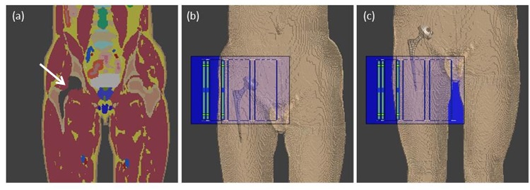
A typical titanium hip prosthesis was modelled and placed in a modified human anatomical model, ‘Duke’ from the virtual family10, with a resolution of 2x2x2 mm3 (Figure 1). A novel custom 8-channel hip coil11 was modelled in commercial software Sim4Life12 (ZMT, Zurich, Switzerland), which was used for both electromagnetic and thermal simulations (using the Finite-Difference Time Domain (FDTD) and the Pennes’ bioheat equation, respectively). The resulting electric fields were exported to Matlab (Mathworks, Natick, Massachusetts) and interpolated on a 3 mm isotropic grid for SAR calculations. The Q-matrix13 of each model was calculated and averaged over exactly 10g14.
The ratio between the maximum SAR10g in a two-voxel layer around the implant and the SAR10g in the rest of the model was optimized to find scenarios where the implant was one of the main causes of heating. SAR10g was first calculated with 1000 different RF shims, with equal magnitudes and random phases. The shims giving the maximum ratios were then used as starting points in a pattern search algorithm. Ten shims were selected, where SAR10g close to the metal implants ranged from 60% to 100% of the global maximum SAR10g.
The input power of the thermal simulations was then scaled so that the global maximum SAR10g was 20 W/kg, which corresponds to a 100% duty cycle at the IEC limit for extremities3. The ambient temperature was set to 24˚C, and core temperature to 37˚C. A Dirichlet thermal boundary was defined at the external air/tissue boundary with a heat transfer coefficient of 10 W/m2/K. The first 40 minutes of simulations were used to reach temperature equilibrium, followed by 6 minutes of RF exposition15.
Because it was expected that the local SAR close to the metal implant would be focused in small volumes16, a novel method of adaptive mass-averaging SAR was developed to increase the sensitivity of the SAR estimation. Specifically, a smaller mass of tissue was averaged when at least 1% of the 10g-averaging volume overlapped with the implant (excluded from the averaging). In order to find the optimal value of this second averaging mass close to the implant, masses from 1g to 9g were tested. The reliability of adaptive mass-averaging SAR to predict local heating was compared to conventional SAR10g.
Results
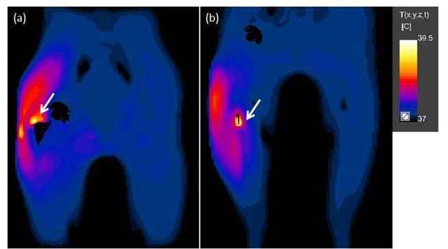
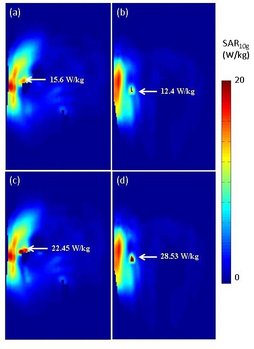
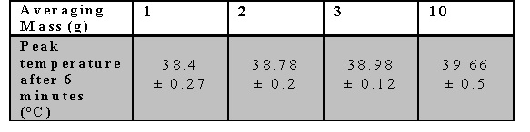
The temperature maps from positions 1 and 2, figure-2, display examples of the locations of RF heating in cases where SAR10g was only 78% and 62% of the global maximum, respectively. The corresponding SAR10g maps, figures-3a&3b, failed to predict both the location and magnitude of RF heating. After 6 minutes of exposure, the peak temperature was above 39˚C, the maximum temperature according to IEC guidelines3. Table 1 shows the range of peak temperatures after 6 minutes of heating; however, it was found that only when the averaging masses were ≤3g were they able to predict the same location of heating as the thermal simulations. An averaging mass of 2g in the tissues surrounding the implant allowed a more accurate prediction of the location of the hot spots compared to SAR10g, Figure 3c and 3d, and limited the heating to below 39˚C after 6 minutes when scaled to 20 W/kg.Discussion and Conclusion
This study shows that SAR10g delivers substantially different results compared to thermal simulations when used around hip prostheses. Although alternatives to SAR10g exist (temperature, thermal dose17), they will take time to be widely used. Adaptive 2g-10g mass-averaged SAR (adSAR2g/10g) is potentially a more reliable alternative, and could be used with current RF monitoring methods, such as virtual observation points (VOPs)18, after experimental validation with different implants and coils.Acknowledgements
Aurelien Destruel acknowledges Siemens Healthcare Pty Ltd for providing funding for a PhD scholarship and ZMT for providing the free academic license of the software Sim4Life. Markus Barth acknowledges funding from ARC Future Fellowship grant FT140100865. The authors acknowledge the facilities of the National Imaging Facility at the Centre for Advanced Imaging, University of Queensland.References
1. Kurtz S, Ong K, Lau E et al. Projections of primary and revision hip and knee arthroplasty in the United States from 2005 to 2030. J Bone Joint Surg Am 2007;89(4):780-785.
2. ASTM. Standard F2182-11a, 2011, standard test method for measurement of radio frequency induced heating on or near passive implants during magnetic resonance imaging. West Conshohocken, PA: ASTM International 2011.
3. Commission IE. Medical electrical equipment, Part 2: particular requirements for the basic safety and essential performance of magnetic resonance equipment for medical diagnosis. IEC 60601-2-33 2010.
4. Powell J, Papadaki A, Hand J et al. Numerical simulation of SAR induced around Co-Cr-Mo hip prostheses in situ exposed to RF fields associated with 1.5 and 3 T MRI body coils. Magn Reson Med 2012;68(3):960-968.
5. Liu Y, Chen J, Shellock FG et al. Computational and experimental studies of an orthopedic implant: MRI-related heating at 1.5-T/64-MHz and 3-T/128-MHz. J Magn Reson Imaging 2013;37(2):491-497.
6. Muranaka H, Horiguchi T, Ueda Y et al. Evaluation of RF heating on hip joint implant in phantom during MRI examinations. Nihon Hoshasen Gijutsu Gakkai Zasshi 2010;66(7):725-733.
7. Collins CM, Liu W, Wang J et al. Temperature and SAR calculations for a human head within volume and surface coils at 64 and 300 MHz. J Magn Reson Imaging 2004;19(5):650-656.
8. Wang Z, Lin JC, Mao W et al. SAR and temperature: simulations and comparison to regulatory limits for MRI. J Magn Reson Imaging 2007;26(2):437-441.
9. Murbach M, Zastrow E, Neufeld E et al. Heating and Safety Concerns of the Radio-Frequency Field in MRI. Current Radiology Reports 2015;3(12):1-9.
10. Christ A, Kainz W, Hahn EG et al. The Virtual Family--development of surface-based anatomical models of two adults and two children for dosimetric simulations. Phys Med Biol 2010;55(2):N23-38.
11. Jin J, Weber E, O'Brien K et al. An 8-channel pTx transceive coil for hip imaging at 7 T. 2017; Honolulu, HI, USA.
12. Sim4Life by ZMT, www.zurichmedtech.com.
13. Graesslin I, Homann H, Biederer S et al. A specific absorption rate prediction concept for parallel transmission MR. Magn Reson Med 2012;68(5):1664-1674.
14. Caputa K, Okoniewski M, Stuchly MA. An algorithm for computations of the power deposition in human tissue. Ieee Antennas and Propagation Magazine 1999;41(4):102-107.
15. Massire A, Cloos MA, Luong M et al. Thermal simulations in the human head for high field MRI using parallel transmission. J Magn Reson Imaging 2012;35(6):1312-1321.
16. Mattei E, Calcagnini G, Censi F et al. A Numerical Method for MRI Induced Heating Evaluation in Subjects Implanted with Metallic Wires. 2009. Springer. p 243-244.
17. van Rhoon GC, Samaras T, Yarmolenko PS et al. CEM43 degrees C thermal dose thresholds: a potential guide for magnetic resonance radiofrequency exposure levels? Eur Radiol 2013;23(8):2215-2227.
18. Eichfelder G, Gebhardt M. Local Specific Absorption Rate Control for Parallel Transmission by Virtual Observation Points. Magnetic Resonance in Medicine 2011;66(5):1468-1476.
Figures