5442
Quasi MR-imaging Artefact Free ECoG and Intracortical Electrodes1Dep. of Microsystems Engineering, University of Freiburg, Freiburg, Germany, 2Dep. of Mechanical Engieneering, San Diego State University, United States, 3Dep. of Radiology, University Medical Center Freiburg, Germany
Synopsis
The combination of implantable neural electrodes and fMRI holds great potential for better understanding the human brain. However, the image acquisition - especially in the vicinity of the implants - is compromised by artifacts caused by metal components. In this work we address this issue by studying different types of devices in terms of designs and materials, and by quantifying their MRI artifacts. Doing so we demonstrate the quasi artifact-free behavior of a hybrid probe combining surface and penetrating carbon electrodes into a single sheet of polyimide, after comparing it with conventional implants in high field MRI and clinical fMRI.
Purpose/Rational
Neural implants like deep brain stimulation (DBS) and electrocorticography (ECoG) devices, in combination with functional magnetic resonance imaging (fMRI), provide new diagnostic value for a better understanding of the brain. Epilepsy research, for example, largely benefits from getting information on the organization of distributed epileptic networks and consequently can investigate the underlying local neurovascular coupling1.
These neural implants are conventionally micro-fabricated and feature metal layer thicknesses in the order of microns, which usually cause severe MRI artifacts. In particular fMRI sequences such as the echo planar imaging (EPI) are especially sensitive to metals2. As an example, signal dropout due to artifacts within 20 mm (at 3 T) of a commercially available 64 platinum grid electrode (equivalent to ~90 cm³ of the total human brain volume) was reported2.
Although artifact reduction may be accomplished through more sequence optimization, this time consuming effort with different circumstances in every patient has little potential benefit2.
To overcome the issue of imaging impairment in MRI, we investigated new implant designs by focusing on their materials and manufacturing methods. First, we compared imaging artifacts of conventional ECoG electrodes with thin-film platinum electrodes in high field MRI. Subsequently, we performed MRI of both a thin-film hybrid device combining surface and penetrating carbon electrodes and a conventional DBS probe, using clinical settings and structural and functional imaging sequences.
Methods
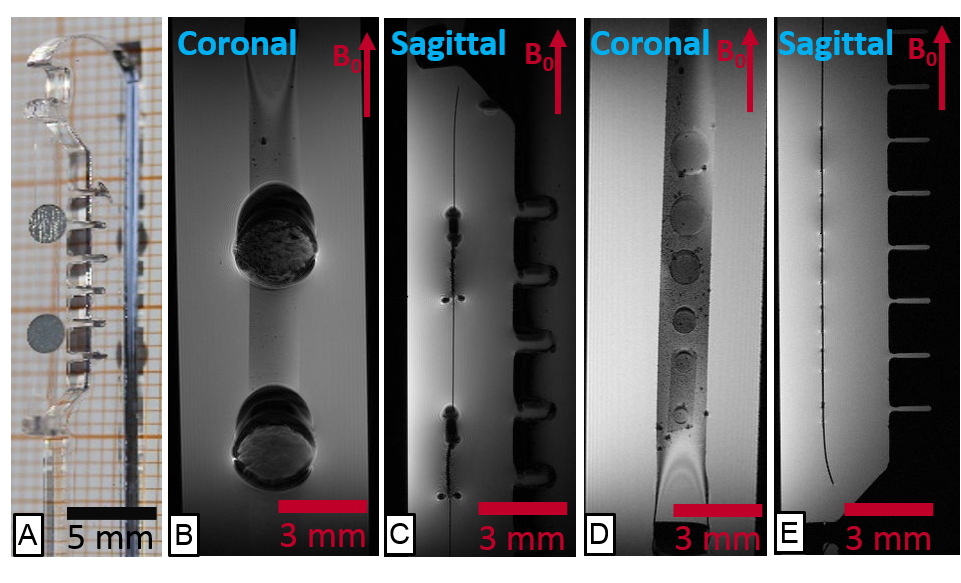
To represent conventional ECoG electrode technology, 25 µm thick platinum electrodes with a diameter of 2 mm were fabricated according to 3. For studying the thin-film platinum electrode counterparts in high field MRI, electrodes of various diameters were fabricated with a thickness of only 300 nm and following the procedure described in 4. Samples were placed on a silicone rubber strip and mounted on a polymethyl methacrylate (PMMA) sample holder (Figure 1A). Then the sample holders were immersed in water and imaged using a 7 T Bruker BioSpec70/20 system with cryocoil, running a 3D gradient echo sequence.
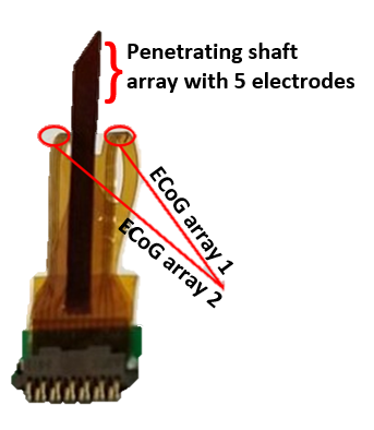
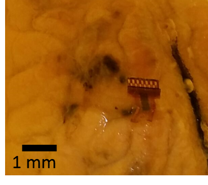
A thin film hybrid device combining ECoG and intracortical electrodes into a single polyimide sheet was fabricated according to 5 and is shown in Figure 2. This device is made of glassy carbon (GC) electrodes and gold tracks on a flexible polyimide substrate. The hybrid probe was implanted into a sheep brain preserved in formaldehyde (Figure 3), together with a commercially available 3389 Medtronic® DBS lead for comparison. Clinical MRI was taken using a 1.5 T Siemens Avanto with a flex knee coil, running a 3D T1w MPRAGE sequence and a 2D segmented spin-echo EPI sequence.
Results
Figure 1 depicts the high resolution MRI comparison of conventional to thin film electrodes.
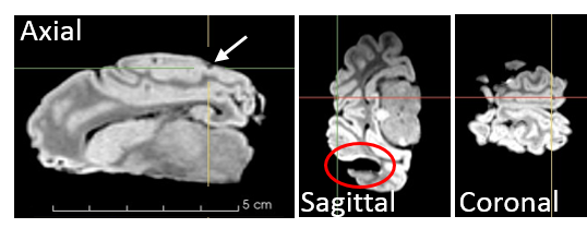
Figure 4 shows a structural MR-image of the preserved sheep brain implanted with the hybrid GC device and conventional DBS probe. The hybrid electrode is shown in all three views highlighted by the slice intersection lines. The artifact size resembles the implant size, although the resolution is too poor to depict details of the device. The imaging artifact of the DBS electrode is visible only in the sagittal view, however the artifact size (~5 mm) is about three times larger than the 1.27 mm-diameter electrodes.
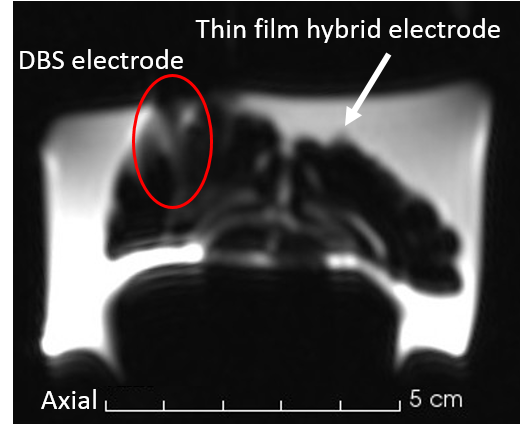
Figure 5 illustrates the results of a 2D segmented spin-echo EPI, a typical fMRI sequence. It compares the thin-film hybrid device with a conventional DBS probe using common clinical fMRI settings.
Discussion
The comparison between the conventional ECoG electrodes (25 µm Ø) and the thin-film Pt ones (300 nm Ø) clearly shows the influence of material thickness on MRI artifacts. As expected, this transfers to the clinical setting, where the artifact in Figure 4 caused by the implanted thin film electrode is with 2 mm the size of the electrode itself. This is also due to the replacement of platinum by gold and glassy carbon as both materials have a lower magnetic susceptibility. Contrarily, the DBS electrode shows artifacts significantly larger than its features, which hinders exact localization in MRI and demonstrates the reduction of diagnostic value in fMRI. The MR-image acquired with the EPI sequence demonstrates instead how the hybrid probe can be considered quasi artifact-free.
Conclusion
These experiments show that the combination of thin film electrodes with fMRI is very promising with respect to artifact interference as compared to conventional implant technology such as conventional ECoG and commercial DBS electrodes. These findings add another advantage to the great potential of hybrid probes in future neuro-prosthetic applications.Acknowledgements
We thank Dr. Juan Ordonez for the DBS electrode and Dr. Mortimer Gierthmuehlen for providing the sheep brain.
This work was funded within the Cluster of Excellence "BrainLinks-BrainTools" by the German Research Foundation (DFG ExC1086).
References
1. Vulliemoz S, Carmichael D.W, Rosenkranz K, et al. Simultaneous intracranial EEG and fMRI of interictal epileptic discharges in humans. Neuroimage. 2011:54(1), 182-190.
2. Boucousis S.M, Beers C.A, Cunningham C.J, et al. Feasibility of an intracranial EEG–fMRI protocol at 3T: Risk assessment and image quality. Neuroimage. 2012:63(3), 1237-1248.
3. Erhardt J.B, Leupold J, Fuhrer E, et al. Influence of Pt/Ir electrode thickness on magnetic resonance imaging susceptibility artefacts. Annual Conference of the German Society for Biomedical Engineering, Biomedical Engineering / Biomedizinische Technik. 2015:60, s1,: s193–s226
4. Rubehn B, Bosman C, Oostenveld R, et al. A MEMS-based flexible multichannel ECoG-electrode array. Journal of neural engineering. 2009;6(3), 036003.
5. Vomero M, et al. A novel pattern transfer technique for mounting glassy carbon microelectrodes on polymeric flexible substrates. Journal of Micromechanics and Microengineering 2016:26.2, 025018
Figures