5441
Real-time measuring of active medical devices malfunction, rectification and induced gradient voltages during MRI exam: low-frequency voltage sensor for MRI safety test.Thérèse Barbier1,2, Sarra Aissani1, Nicolas Weber1, Julie Kabile1, Cédric Pasquier1, and Jacques Felblinger1,3
1IADI, U947, INSERM, Université de Lorraine, Nancy, France, 2Axon' Cable, Montmirail, France, 3CIC 1433 Innovation Technologique, INSERM, CHRU Nancy, Nancy, France
Synopsis
An MR compatible low-frequency voltage probe design will be presented. This tool is used to monitor active implanted medical devices during MRI exam as well as measuring the gradients switching induced voltage or RF rectification thus allowing MRI safety assessment and combined field tests.
Purpose:
To evaluate the MR safety of active implantable medical devices (AIMD) during MRI scans which implies the measurement of low frequency voltages such as: The AIMD stimulation signals, RF rectified pulse and gradients induced voltage.Methods:
An MR compatible low-frequency voltage probe was designed on a small (20 mm x 30 mm) PCB. A non-magnetic battery was used as a circuit supply. Both were mounted inside a brass shield enclosure (cylinder Ø 33 mm, height 50 mm) to protect the circuit from radiofrequency noise. In order to achieve sufficient RF interference suppression, feed-through capacitors were assembled into shield enclosure. The block diagram shown in figure 1 summarizes the different circuit stages. In fact, after radiofrequency filtering the signal amplitude is diminished by a voltage divider and sent to a high precision high input impedance instrumentation amplifier. A summing amplifier was used to shift the voltage level and an anti-aliasing filter with a cutoff-frequency of 40 kHz was added prior to the analog to digital converter (12 bits) that sample at a frequency of 100 kHz. The digital signal was then used to drive a light emitting diode and the optical signal was carried outside the MRI room to the real-time acquisition. This latter one is based on the data acquisition module, NI PXI-7833R FPGA, with a sampling frequency up to 40 MHz. A LabVIEW RT 8.5 (National Instruments, USA) interface was programmed to decode, display and save data. MRI experiments were carried on 1.5 T (64 MHz) whole-body MR scanner (Signa HDx, General Electric Healthcare, Milwaukee, WI, USA). The device under test was a commercial pacemaker with two 52 cm length leads connected to the header. The PM was programmed in MRI mode: unipolar pacing polarity which means that the induced voltage was always measured between the pacemaker Ventricular chamber tip and case. For our tests, we have used a rectangular plexiglass phantom (30.5 cm x 37cm x 34 cm) filled with tissue equivalent gel that simulate the electrical properties of body tissue at 64MHz 1 (dielectric constant, ε = 80; conductivity, σ = 0.47 S.m−1). The pacemaker under test and the voltage probe were fixed to a Teflon grid which was positioned at the center of the phantom. The leads, on the other hand, were attached to the Teflon grid support to form a loop as shown in the photograph of figure 2. Finally, the phantom was placed 35 cm away from the MR isocentre in the region of the highest spatial magnetic gradient. MRI Gradient echo sequence was modified and played with different slew (47.8, 51.2, 55, 59.5, 64.7, 71, 78.6, 88, 100 and 115.8 T/m/s).Results:
Figure 3 shows the pacemaker pulse and the induced gradients voltage for a slew rate of 88 T/m/s. The induced peak-to-peak voltage measured by the LF probe across the pacemaker tip and case as a function of the slew rate is reported in figure 4.Discussion:
Few studies have shown interest in the study of gradients induced voltage 2. In comparison to Mattei et al. low-frequency induced currents sensor 3, the LF probe offers a 100 kHz sampling rate allowing measurement of gradients induced voltage with a frequency up to 10 kHz while maintaining good signal integrity. Furthermore, the RF noise is highly attenuated thanks to the shield enclose and use of feed-through capacitors. Considering the gradients trapezoidal waveform, the induced voltage is a rectangular waveform at the same frequency as shown in figure 3. Besides, the pacemaker pulse was monitored with no attenuation (before and after) MRI scan inside the phantom. Furthermore, the linear proportionality of the induced voltage as a function of slew rate is confirmed by the result of figure 4.Conclusion:
The proposed voltage sensor exhibit a measurement range of ±15 V with an amplitude resolution of 7 mV and temporal resolution of 10 µs. It has a high DC input impedance and a high attenuation of 46 dB at 64 MHz. The characteristics of this present low-frequency voltage probe allow its use to study the gradient induced voltage impact on the AIMD with leads and also used in the combined fields test for MR safety assessment procedure for AIMD according to ISO standards 4.Acknowledgements
The authors thank the Region Grand Est and FEDER for financial support under SpinE grant.References
1. ASTM F2182-11a, Standard Test Method for Measurement of Radio Frequency Induced Heating On and Near Passive Implants During Magnetic Resonance Imaging, 2011. 2. Tandri H, Zviman MM, Wedan SR, Lloyd T, Berger RD, Halperin H. Determinants of Gradient Field-Induced Current in a Pacemaker Lead System in a Magnetic Resonance Imaging Environment. Heart Rhythm 2008;5:462–468. 3. Mattei E, Censi F, Triventi M, Napolitano A, Genovese E, Cannatà V, Calcagnini G. An Optically Coupled Sensor for the Measurement of Currents Induced by MRI Gradient Fields into Endocardial Leads. Magn. Reson. Mater. Phys. Biol. Med. 2015;28:291–303. 4. ISO/TS 10974:2012, Assessment of the safety of magnetic resonance imaging for patients with an active implantable medical device.Figures
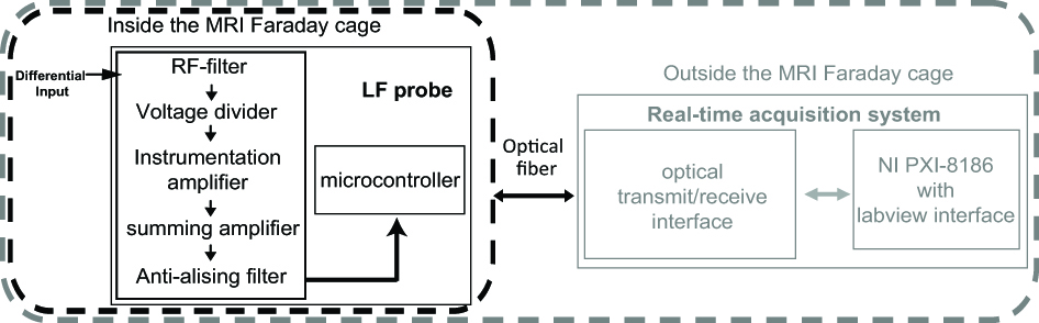
Acquisition system block diagram. The LF probe
is placed inside the MR bore and data are acquired, converted and transmitted
into light pulses by optical fibers to the controller unit located outside the
Faraday cage

Rectangular phantom with the
Teflon grid used for gradient tests, a) its schematic, b) photograph of the
rectangular phantom with the pacemaker and the LF probe fixed to the grid, c)
LF probe connected to the pacemaker tip/case and fixed to the Teflon grid where
a loop was formed using the leads with an of area ≈ 194.7 cm² to maximize
gradient magnetic field coupling.
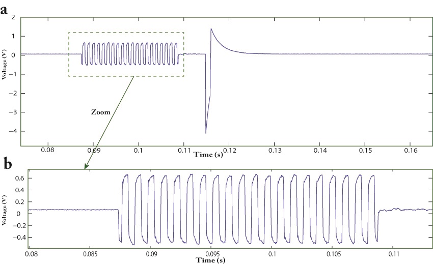
Measured induced voltage during MRI gradient
sequence corresponding to a slew rate of 88 T/m/s, a) between the Pacemaker tip
and its case, b) Zooming on the gradients
induced voltage between the Pacemaker tip and its case.
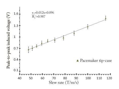
Induced peak-to-peak voltage
measured for different slew rates during MRI gradient sequence between the
pacemaker tip and its case (unipolar pacing mode) where a loop was formed using
the leads.