5432
Higher is better: High peak and high average RF power transmit/receive switch for an integrated RF heating applicator operating at 297 MHz (7.0 Tesla)Yiyi Ji1, Werner Hoffmann2, Michal Pham1, Celal Oezerdem1, Helmar Waiczies3, Thoralf Niendorf1,3,4, and Lukas Winter1
1Berlin Ultrahigh Field Facility (B.U.F.F.), Max Delbrück Center for Molecular Medicine in the Helmholtz Association (MDC), Berlin, Germany, 2Physikalisch-Technische Bundesanstalt (PTB), Berlin, Germany, 3MRI.TOOLS GmbH, Berlin, Germany, 4Experimental and Clinical Research Center (ECRC), a joint cooperation between the Charité Medical Faculty and the Max Delbrück Center for Molecular Medicine in the Helmholtz association
Synopsis
An integrated RF heating system utilizes the MR spin excitation frequency together with dedicated RF antennas for controlled RF heating and MR imaging in an integrated system. Operating the MR power amplifier for both RF heating and MR imaging applications simultaneously requires customized transmit/receive (Tx/Rx) switches that can handle both high peak powers and high average powers. In this work we designed, built and evaluated a high power Tx/Rx switch for handle MRI and RF heating requirements.
Introduction
Controlled application of thermal dose is of major interest in thermal phenotyping, multimodal RF hyperthermia treatments, thermal drug release and MR safety evaluations [1-3]. An integrated RF heating system utilizes the spin excitation frequency for controlled RF induced heating and MR imaging [4-5]. Operating the MR power amplifier for RF heating and MRI simultaneously requires customized transmit/receive (Tx/Rx) switches, which can protect the preamplifiers from high peak powers and withstand high average power of >50-100W. Traditional Tx/Rx switches commonly use pin diodes to switch between transmit and receive modes, which constraints the average power to <25W. To address this shortcoming we designed, built and evaluated a high power Tx/Rx switch tailored to be driven at much larger average power.Materials and Methods
The schematic of the proposed high power Tx/Rx switch is presented in Fig.1a. It consists of three λ/4 stubs assembled with semi-rigid coaxial cables for 297MHz and two pin diodes (D1: Tx path, D2: Rx path, MA4P7441F-1091T, Macom, MA, USA). A LC resonant circuit tuned to 297MHz is placed between each pin diode and λ/4 stub to afford maximum isolation between the Tx and Rx paths. The Tx and Rx path circuits were placed in double shielded compartments to increase isolation (Fig.1b). During Tx mode, a short in point 1 and 4 (Fig.1a) is transformed into an open in point 2 and 3 by λ/4 stubs so that all RF signal is routed into the RF coil. During Rx mode, an open in point 4 translates into a short in point 3 and an open in point 2, directing the signal into the Rx port. Temperature in the Tx/Rx switch circuit while driving Pavg=85W was accessed with an infrared camera (Ti25, Fluke, WA, USA). An experimental setup comprising a rectangular phantom (90×180×260mm3) with cylindrical sample holders and a bow tie dipole antenna for transmission [4] (Fig.2a-b) was used to examine the suitability of the high power Tx/Rx switch for MR imaging and RF heating in a B0=7.0T MR system (Magnetom, Siemens Healthcare, Erlangen, Germany). MR images were acquired using a gradient echo sequence (FOV=(240×240)mm2, TR=8.6ms, TE=4.7ms, spatial resolution=(1.0×1.0×5.0)mm3) with i) the proposed high power Tx/Rx switch and ii) a conventional Tx/Rx switch (Stark Contrasts, Erlangen, Germany). RF heating was accomplished using the MR RF power amplifier (8kW peak power, 4ms rect-pulse, U=285V) and TR=40ms resulting in a duty cycle of 10%. This setup afforded a measured average power of 70W at the antenna. The heating paradigm consisted of 3×3min RF heating interleaved with 2D MR thermometry (MRTh) acquisitions. 2D MRTh was conducted using a proton resonance frequency shift method [6] and dual gradient-echo technique [7-8] (FOV=(300×300)mm2, TR=61ms, TE1=2.26ms and TE2=11.44ms, spatial resolution=(1.5×1.5×4)mm3). A fiber optic temperature sensor (Omniflex, Neoptix, Quebec, Canada) placed 5 mm below the RF antenna was used as reference.Results
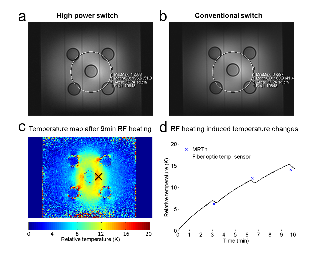
The proposed Tx/Rx switch provided an isolation of -29dB between Tx port and Rx port during the transmission mode (Table 1). Insertion loss was -0.3dB between the Tx port and the antenna in transmission mode and -0.3dB between the antenna and the Rx port in reception mode (Table1). After 3min driving Pavg=85W, Tmax in the circuit was 49.5°C in the pin diode of the Tx compartment (Fig.3b). MRI exploiting the proposed high power Tx/Rx switch and coventional Tx/Rx switches yielded similar image quality (Fig.4a-b). After 9 minutes of RF heating, the MR thermometry map (Fig.4c) acquired with the switch showed an increase of ΔT=14.8°C at the position of the fiber optic temperature sensor for which ΔT=14.1°C was registered.Discussion and Conclusion
The proposed high power Tx/Rx switch design provided high isolation and low insertion loss. By incorporating λ/4 stubs, high transmitter voltages are blocked effectively from the pin diodes, which afford high power operation. Driving a Pavg=85W for 3min, the temperature in the circuit of the switch didn’t exceed 50°C, showing low internal losses. Benchmarked against a conventional Tx/Rx switch, the high power Tx/Rx switch provided similar image quality which demonstrates its compatibility with the needs of MRI. For the RF heating experiment, the proposed switch handled an average power of 70W and MRTh, for which the temperature measurements were well correlated to those from the fiber optic temperature sensor. In conclusion, the proposed high power Tx/Rx switch is suitable for MR imaging and RF heating purposes at 297MHz, which bodes very well for thermal MR applications.Acknowledgements
This work was funded in part (Y.J., H.W., T.N., L.W.) by the German Federal Ministry of Education and Research (KMU-innovativ: Medizintechnik, FKZ 13GW0102A, FKZ 13GW0102B).References
[1] Issels RD, et al.,. Lancet Oncol. 2010;11(6):561-70, [2] de Smet M, et al., Invest Radiol. 2013;48(6):395-405, [3] Murbach M, et al., Magn Reson Med. 2013;71(1):421-31, [4] Winter L, et al., PLOS ONE 2013, 8(4):e61661, [5] Winter L, et al., Radiation Oncology, 2015;10(1):201, [6] Ishihara Y, et al., Magn Reson Med 1995, 34(6):814-823, [7] Rieke V, J Magn Reson Imaging 2008, 27: 376–390, [8] Wonneberger U, et al., J Magn Reson Imaging 2010, 31(6):1499-1503Figures
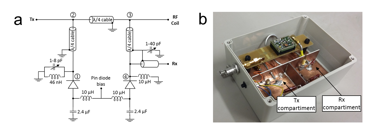
Figure 1 – a) Circuit diagram of the high power Tx/Rx switch. D1: pin diode of the Tx path,
D2: pin diode of the Rx path. b) The
constructed switch. Tx path circuit and Rx path circuit were isolated with
double shielded walls.
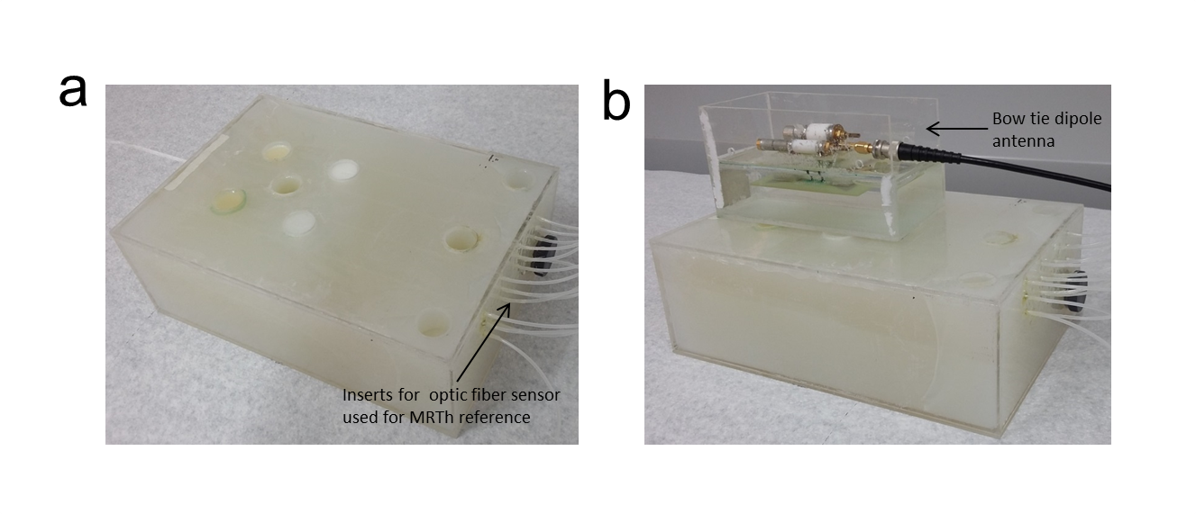
Figure 2 – a)
Rectangular phantom (90 × 180 × 260 mm3) with cylindrical sample
holders used in the experiments. b)
Phantom setup including the bowtie antenna connected to the high power TX/RX
switch used for MRI and RF heating experiments.
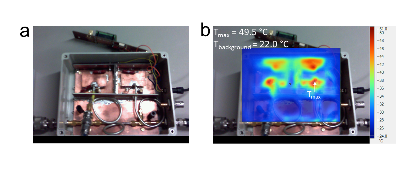
Figure 3 – a) Photograph
of the switch while driving Pavg = 85 W. Note that compared to Fig.1b the
preamp circuit was removed. b)
Infrared image superimposed to photograph of the Tx/Rx switch shown in a). The
infrared image shows temperature distribution in the circuit after 3 min
driving Pavg of 85 W. The maximum temperature (Tmax) was localized
in the pin diode of transmission compartment.
Figure
4 – a) Gradient
echo image of a coronal slice of the phantom acquired with the high power
switch and with b) a conventional
switch. c) Coronal slice of the MRTh
temperature distribution. The slice was located 5 mm below the antenna where
a fiber optic temperature sensor was placed (black cross) d) RF heating induced temperature changes obtained from
fiber optic temperature sensor measurements and MRTh.
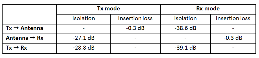
Table 1 – Isolation and insertion loss of the proposed high power Tx/Rx switch.