5430
Active catheter tracking for cardiac MR thermometry during radiofrequency ablationSolenn Toupin1,2, Valéry Ozenne1, Pierre Bour1,3, Rainer Schneider4, Matthieu Lepetit-Coiffé2, Baudouin Denis de Senneville5, Erik Dumont3, Pierre Jaïs6, and Bruno Quesson1
1Imaging, IHU Liryc (Electrophysiology and heart modeling institute), Bordeaux, France, 2Siemens Healthineers France, Saint-Denis, France, 3IGT (Image Guided Therapy), Pessac, France, 4Siemens Healthineers, Germany, 5IMB (Mathematics Institute of Bordeaux), Bordeaux, France, 6Electrophysiology and Ablation Unit, IHU Liryc (Electrophysiology and heart modeling institute), Bordeaux, France
Synopsis
Cardiac MR thermometry provides a real-time monitoring of temperature distribution in myocardium during catheter-based radiofrequency ablation. One major challenge of this technique is the compensation of motion induced by the heart contraction and respiration. In this study, we propose to perform fast multi-slice proton resonance frequency (PRF) shift MR thermometry combined with a real-time slice following technique, based on active catheter tracking. Performance of this approach was evaluated in vitro on a moving agar gel phantom.
PURPOSE
Catheter-based radiofrequency (RF) ablation is widely used clinically for the treatment of cardiac electrical disorders. However, a significant rate of recurrence (~30%) has been reported due to suboptimal RF energy deposition into the myocardium1 and lack of real-time lesion visualization. Fluoroscopic guidance provides limited information on the actual lesion during the procedure due to a poor soft-tissue contrast and restrictions in X-ray exposure time. Thus, cardiac MR thermometry using the proton resonance frequency (PRF) shift technique has been suggested to map the temperature distribution and to compute the accumulated thermal dose during RF ablation. Recent studies proposed to compensate for cardiac motion (myocardial contraction and breathing) by positioning the imaging slices in the main direction of displacement2 or by updating the slices position according to the respiratory trace recorded at the liver-lung interface using an echo-navigator3. In this study, we propose to actively track the catheter position and to update the MR-thermometry slice position accordingly. Temperature stability of the proposed method was evaluated in vitro on a moving agar gel (without heating). Then during a RF ablation with the same experimental parameters.METHODS
A MR-compatible catheter (MRI Interventions, Irvine, CA, U.S.A.) equipped with four MR receivers (Figure 1-A) was interfaced with a 1.5 T MR scanner (Magnetom Aera, Siemens Healthineers). A multi-slice single-shot echo-planar imaging (EPI) pulse sequence was interleaved with a catheter tracking scheme. It consisted in a non-selective RF pulse applied before a linear gradient was played along one direction during signal reception. This scheme was repeated 3 times with gradients applied along 3 orthogonal directions (Figure 1-B). The signal collected by each micro-coil of the catheter showed a sharp peak in frequency, whose position is proportional to the spatial location of the micro-coil along the applied gradient direction (Figure 1-C). The detected 3D position of the coil at the catheter tip was used to update the following stack of EPI slices on the fly. Despite the compensation of the in-plane (for coronal and sagittal orientations) and out-of-plane (for transverse orientation) motion using catheter tracking, phase images remained corrupted by local magnetic field changes associated with motion. These artifacts were corrected on-line by performing phase modeling based on the updated slice position, as reported recently by Wang et al.4. A periodic motion in the z-axis direction (head-feet) of an agar gel was induced by a home-made rocker, with an amplitude of 10 mm, higher than the slice thickness (3 mm). Temperature mapping was first evaluated without heating to calculate the temporal standard deviation of temperature σT over three min of acquisition with different slices orientation (parallel or perpendicular to the direction of motion). The same protocol was then repeated during RF ablation at 4 W for 20 s.RESULTS
This new cardiac thermometry pipeline was operated on the fly with a temporal resolution of ~100 ms per image and a voxel size of 2x2x3 mm3. The measurement of the temperature quality without heating showed similar results whatever the slice orientation, with a temporal standard deviation σT below 2°C (Figure 2, A-C). Monitoring of temperature during RF ablation was successfully performed using the proposed method. Figure 3 shows the maximal temperature changes at the end of the RF delivery during rocker-driven motion.DISCUSSION
This new MR thermometry method using active catheter tracking shows good performances in presence of in-plane and through-plane motions. This method allows automatic positioning of the imaging slices on the catheter in real-time to continuously visualize the temperature distribution. In the current setup, residual electromagnetic interferences (harmonics of the RF ablation signal) were observed on catheter’s coil signal at high RF power that disturbed the catheter tracking performances. Further in vivo evaluation on a large animal model are envisioned once this technological issue is solved.CONCLUSION
The combination of catheter tracking and MR thermometry allows accurate thermometry in presence of motion. This method is promising for further monitoring of cardiac RF ablation, avoiding any constraint on image orientations nor assumption on scaling factor between the liver motion followed by an echo navigator and the heart motion.Acknowledgements
No acknowledgement found.References
1Tanner et al., J Cardiovas Electrophysiol, 2010
2Ozenne et al., Magn Reson Med, 2016
3de Senneville et al., NMR Biomed, 2012
4Wang et al., J Magn Reson Imaging, 2015
Figures
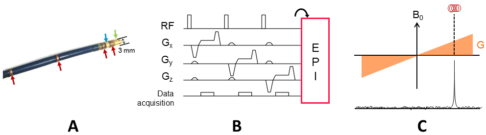
Figure 1: Active catheter
tracking interleaved with the MR thermometry imaging pulse sequence. (A) A catheter
equipped with four micro-coil receivers (red arrows) and two EP electrodes
(green and blue arrows) including the ablation tip (green arrow). (B) Basic single-echo
catheter tracking scheme, used to detect the 3D coordinates of the tip
micro-coil. (C) The signal received by the micro-coil used to calculate the
spatial location of the micro-coil along the applied gradient direction.
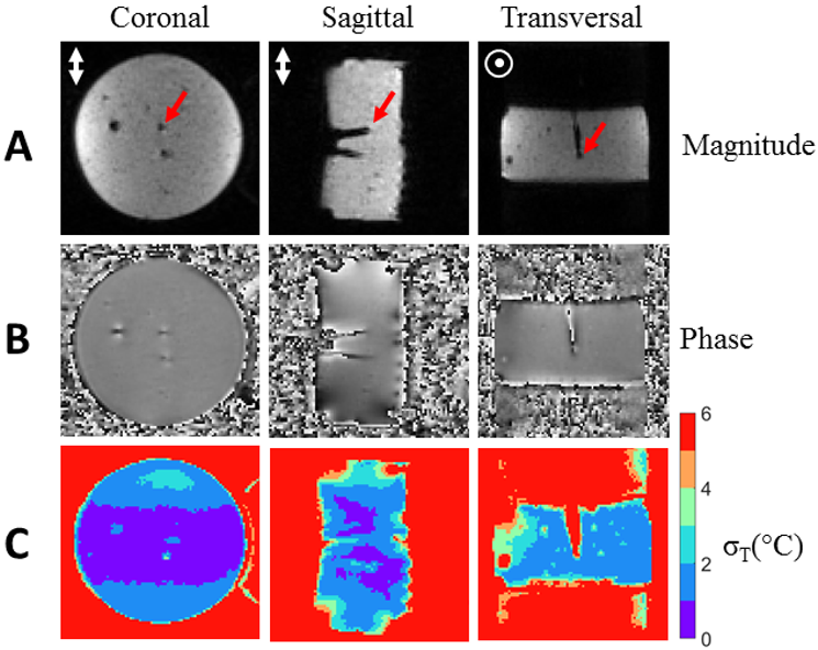
Figure 2: MR thermometry on a moving phantom using
active catheter tracking. The motion was
in-plane to coronal and sagittal imaging slices whereas it was through-plane
the transversal imaging slice. The catheter is visible on magnitude (A, red
arrows) and phase images (B). Temporal standard deviation σT
(C) was computed over 3 min of acquisition time.
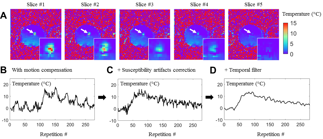
Figure 3: Simultaneous monitoring of a RF
heating (4W for 20s) and catheter tracking on a moving phantom.
(A) Multi-slice temperature maps at the end of the RF delivery. The temperature
evolution of the hottest pixel is plotted after motion compensation without
susceptibility artifacts compensation in (B). The susceptibility artifacts are
corrected using the catheter position given the temperature evolution (C)
without temporal filtering and (D) with temporal filtering (Butterworth
low-pass filter).