5059
Relaxometry via steady-state ring-locked trajectories1Dept. Electrical & Electronic Engineering, University of Melbourne, Melbourne, Australia, 2Dept. Electrical and Computer Systems Engineering, Monash University, Melbourne, Australia, 3IBM Research, Melbourne, Australia
Synopsis
It is known that steady-state ring-locked trajectories are formed on an elliptical manifold under a constant amplitude and constant frequency excitation envelope. Here we demonstrate that the excitation envelope can be expressed in terms of the spin-system parameters and a target steady-state trajectory, providing control of the magnetisation on the steady-state ellipsoid when spin-system parameters, such as the relaxation constants, are known. Conversely, we exploit this relationship between excitation parameters and unknown relaxation constants to develop a volume relaxometry technique, which can potentially be extended to relaxation mapping due to the elliptical nature of balanced SSFP.
Purpose
In this work, we present an excitation envelope to control the steady-state magnetisation on an ellipsoid, and experimentally demonstrate an alternative method for estimating the ratio of relaxation constants. Existing steady-state free precession1 (SSFP) methods such as IR-TrueFISP2,3, DESPOT4,5, DESS6,7 and TESS8 generate relaxation maps via linear regression of signal models dependent on relaxation constants $$$T_1$$$ and $$$T_2$$$. In our method, we apply off-resonance partial saturation pulses and derive a steady-state signal model, which is dependent on excitation off-resonance, in addition to the relaxation constants. We exploit this relationship between excitation parameters and unknown relaxation constants to develop a volume relaxometry technique, which can potentially be extended to relaxation mapping due to the elliptical nature of balanced SSFP9.Theory
A spin-system under constant amplitude RF excitation will reach a steady-state magnetisation on an ellipsoid10 whose shape is defined by the relaxation constants and is influenced by off-resonance effects and imperfect excitation11. We introduce a constant frequency modulation, $$$\omega$$$, to the constant amplitude excitation, $$$|\omega_1^e|$$$, which induces a ring-locked steady-state trajectory on the surface of the ellipsoid (Fig. 1). Given arbitrary values of excitation parameters for relaxation $$$T_1,\,T_2$$$, off-resonance $$$\Delta$$$, frequency modulation $$$\omega$$$, phase offset $$$\theta$$$ and elevation on the steady-state ellipsoid $$$a\in(-1,1]$$$, we define the excitation envelope, $$\gamma\,B_1^e\left(t\right)=|\omega_1^e|\,e^{i\phi\left(t\right)}$$ where $$|\omega_1^e|=\sqrt{\frac{T_2}{T_1}\left(\frac{1-a}{1+a}\right)\Big[\left(\omega+\Delta\right)^2+\left(\frac{1}{T_2}\right)^2\Big]}$$ $$\phi\left(t\right)=\omega\,t+\theta-\tan^{-1}{\left(\frac{1}{T_2\left(\omega+\Delta\right)}\right)}.$$ Under this excitation, a tissue with parameters of relaxation $$$\bar{T_1},\,\bar{T_2}$$$, off-resonance $$$\bar{\Delta}$$$, excitation field inhomogeneity factor $$$B_\text{1}^\text{mod}$$$ and magnetisation at thermal equilibrium $$$M_0$$$ will reach a steady-state ring trajectory with an elevation, $$$\bar{a}$$$, and phase offset, $$$\bar{\theta}$$$, on the ellipsoid defined by: $$M_x=\frac{M_0}{2}\sqrt{\frac{\bar{T_2}}{\bar{T_1}}\left(1-\bar{a}^2\right)}\,\cos{\left(\omega{t}+\bar{\theta}\right)}$$ $$M_y=\frac{M_0}{2}\sqrt{\frac{\bar{T_2}}{\bar{T_1}}\left(1-\bar{a}^2\right)}\,\sin{\left(\omega{t}+\bar{\theta}\right)}$$ $$M_z=\frac{M_0}{2}\left(1+\bar{a}\right)$$ where $$\bar{a}\left(a,\omega,T_1,T_2,\Delta,\bar{T_1},\bar{T_2},\bar{\Delta},{B_\text{1}^\text{mod}}\right)=\frac{1-\beta}{1+\beta}$$ $$\beta={B_\text{1}^\text{mod}}^2\frac{\bar{T_1}\,T_2}{T_1\,\bar{T_2}}\left(\frac{1-a}{1+a}\right)\left[\frac{(\omega+\Delta)^2+\left(\frac{1}{T_2}\right)^2}{(\omega+\bar{\Delta})^2+\left(\frac{1}{\bar{T_2}}\right)^2}\right]$$ and $$\bar{\theta}=\theta-\tan^{-1}{\left(\frac{1}{T_2\left(\omega+\Delta\right)}\right)}+\tan^{-1}{\left(\frac{1}{\bar{T_2}\left(\omega+\bar{\Delta}\right)}\right)}.$$ We have verified this analytical solution using numerical simulations and harmonic balancing12 of the Bloch equations. Elevation on the steady-state ellipsoid can also be expressed in terms of the constant excitation amplitude, $$\bar{a}\left(|\omega_1^e|,\omega,\bar{T_1},\bar{T_2},\bar{\Delta},B_1^\text{mod}\right)=\frac{1-\beta}{1+\beta}$$ $$\beta=\frac{\bar{T_1}}{\bar{T_2}}\left[\frac{|\omega_1^e|^2{B_\text{1}^\text{mod}}^2}{\left(\omega+\bar{\Delta}\right)^2+\left(\frac{1}{\bar{T_2}}\right)^2}\right].$$ We exploit this relationship between unknown tissue parameters, $$$\bar{T_1},\bar{T_2}$$$, and excitation parameters, $$$|\omega_1^e|,\omega$$$, to develop a relaxometry technique.Methods
Two experiments were conducted on a 4.7T Bruker Biospec scanner with an AVANCE III console. An iterative measurement protocol13,14 (Fig. 1) was used to incrementally measure the transverse and longitudinal steady-state magnetisation. In both experiments, field maps and relaxation constants were measured using standard sequences (details below).
Reference relaxometry:
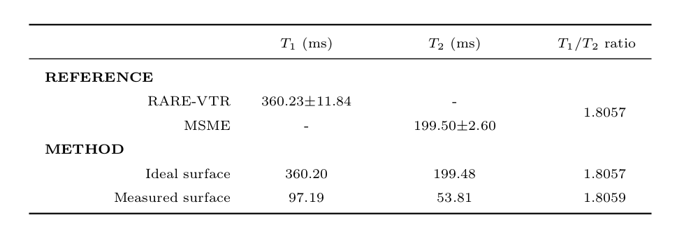
Rapid acquisition with relaxation enhancement with variable repetition time (RARE-VTR) scans and multi-slice multi-echo (MSME) scans were used to measure $$$T_1$$$ and $$$T_2$$$ maps respectively. The measured relaxation maps were spatially averaged to produce a single $$$T_1$$$ and $$$T_2$$$ constant per phantom.
Field Maps:
The distribution of off-resonances, $$$\rho\left(\delta_{B_\text{0}}\right)$$$, was measured using the field-mapping sequence, MAPSHIM (Bruker Biospin). The distribution of excitation field strength, $$$\rho\left(B_\text{1}^\text{mod}\right)$$$, was measured with a $$$B_1$$$ mapping sequence15. Distributions were extracted via a histogram of non-background voxels.
Verification of excitation envelope:
The first experiment applied the excitation envelope, $$$\gamma\,B_\text{1}^\text{e}\left(t\right)$$$, to a spherical phantom of water to demonstrate control of the steady-state magnetisation. Ring-locked trajectories were measured over a range of elevations $$$a$$$ from -0.95 to 1.0 with a 0.05 increment, using a constant excitation frequency $$$\omega$$$=50Hz, measured relaxation constants $$$T_1$$$=3.20s and $$$T_2$$$=2.02s and off-resonance $$$\Delta$$$=0Hz.
Estimation of relaxation constants:
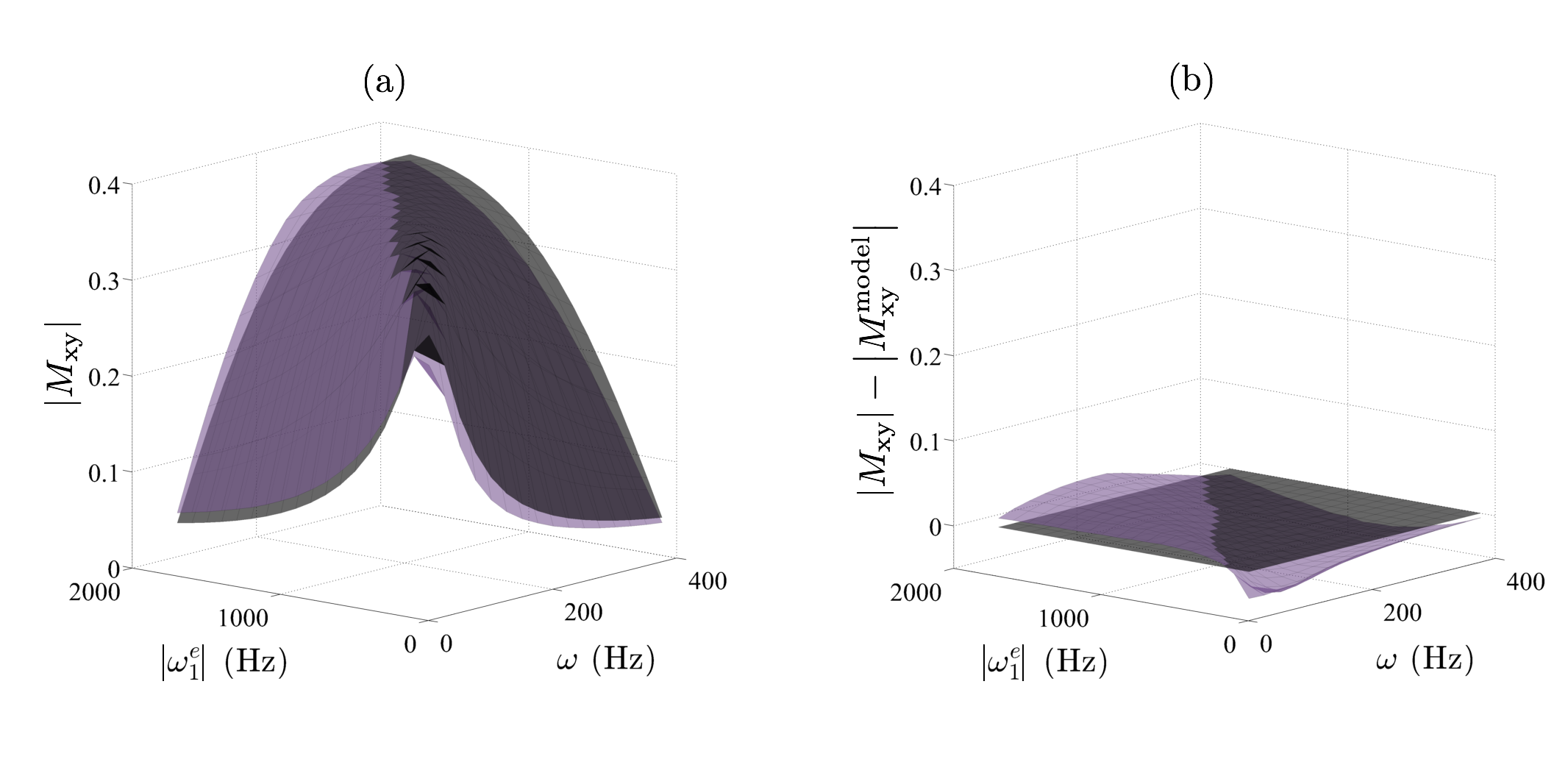
In a second experiment we measured the transverse steady-state magnetisation, $$$\boldsymbol{M}_{xy}^\text{obs}$$$, of a spherical phantom of Gadolinium doped water ($$$T_1$$$=360.23ms, $$$T_2$$$=199.50ms) over a grid of excitation parameters, amplitude $$$|\omega_1^e|$$$ from 100Hz to 1800Hz with a 100Hz increment and frequency $$$\omega$$$ from 25Hz to 400Hz with a 25Hz increment. Relaxation constants were estimated using the objective function, $$\underset{\bar{T_1},\,\bar{T_2}\in[0,\infty)}{\operatorname{minimise}}\,\LARGE{\parallel}\normalsize\left|\boldsymbol{M}^{\text{model}}_{xy}\left(|\omega_1^e|,\omega,\bar{T_1},\bar{T_2}\right)\right|-\left|\boldsymbol{M}_{xy}^\text{obs}\left(|\omega_1^e|,\omega\right)\right|\,\LARGE\parallel_{\normalsize2}$$ where $$\boldsymbol{M}^{\text{model}}_{xy}\left(|\omega_1^e|,\omega,\bar{T_1},\bar{T_2},t\right)=\int\int\,M_{xy}\left(|\omega_1^e|,\omega,\bar{T_1},\bar{T_2},\bar{\Delta}=\delta_{B_\text{0}},B_\text{1}^\text{mod},t\right)\rho\left(B_\text{1}^\text{mod}\right)\rho\left(\delta_{B_\text{0}}\right)\,dB_\text{1}^\text{mod}\,d\delta_{B_\text{0}},$$ and was solved via numerical integration and non-linear least squares optimisation with a non-negativity constraint.
Results & Discussion
The experimentally measured and analytically predicted steady-state trajectories (Fig. 2a-c) form ellipsoids, verifying that the excitation envelope can accurately control the elevation and phase, with minor error (3.1% $$$M_0$$$) in the magnitude of the transverse signal (Fig. 2d). Optimisation of the measured and predicted transverse magnetisation surfaces (Fig. 3a) is used to estimate the relaxation constants. Relaxometry results (Table 1) demonstrate that using the proposed method a ratio of relaxation constants can be accurately estimated. Both relaxation constants can be estimated when using a simulated ideal measurement, but individual $$$T_1$$$ and $$$T_2$$$ estimates were inaccurate in the experimental case due to slight (4.2% $$$M_0$$$) measurement error (Fig. 3b).Conclusion
The proposed excitation envelope is able to control the steady-state ring-locked magnetisation trajectories. A model for steady-state magnetisation response under this excitation was applied as an alternate technique for estimation of the ratio of relaxation constants. Our current work is focusing on reducing measurement error and application of this excitation envelope to an SSFP relaxation parameter mapping method.Acknowledgements
This work was supported by the Australian Research Council, the Elizabeth & Vernon Puzey Scholarship and National ICT Australia.References
1. Carr HY. Steady-State Free Precession in Nuclear Magnetic Resonance. Phys rev. 1958;112(5):1693-1701.
2. Scheffler K, Hennig J. T1 quantification with inversion recovery TrueFISP. MRM. 2001;45(4):720-723.
3. Schmitt P, Griswold MA, Jakob PM, et al. Inversion recovery TrueFISP: quantification of T1, T2, and spin density. MRM. 2004;51(4):661-667.
4. Homer J, Beevers MS. Driven-equilibrium single-pulse observation of T1 relaxation. A reevaluation of a rapid “new” method for determining NMR spin-lattice relaxation times. JMR. 1985;63(2):287-297.
5. Deoni SC, Rutt BK, Peters TM. Rapid combined T1 and T2 mapping using gradient recalled acquisition in the steady state. MRM. 2003;49(3):515-526.
6. Bruder H, Fischer H, Graumann R, et al. A new steady-state imaging sequence for simultaneous acquisition of two MR images with clearly different contrasts. MRM. 1988;7(1):35-42.
7. Welsch GH, Scheffler K, Mamisch TC, et al. Rapid estimation of cartilage T2 based on double echo at steady state (DESS) with 3 Tesla. MRM. 2009;62(2):544-549.
8. Heule R, Ganter C, Bieri O. Triple echo steady-state (TESS) relaxometry. MRM. 2004;71(1):230-237.
9. Hargreaves B. Rapid gradient-echo imaging. JMRI, 2012;36(6):1300-1313.
10. Bloch F. Nuclear induction. Phys rev, 1946;70(7-8):460-474.
11. Abragam A. The principles of nuclear magnetism (No. 32). Oxford university press. 1961.
12. Tahayori B, Johnston LA, Layton KJ, et al. Solving the Bloch equation with periodic excitation using harmonic balancing: application to Rabi modulated excitation. IEEE trans medical imaging. 2015;34(10):2118-2130.
13. Layton KJ, Tahayori B, Mareels IM,et al. Rabi resonance in spin systems: Theory and experiment. JMR, 2014;242:136-142.
14. Korte JC, Layton KJ, Tahayori B, et al. NMR spectroscopy using Rabi modulated continuous wave excitation. Biomed Sig Proc Control. 2016 (in press); 10.1016/j.bspc.2016.10.006.
15. Bergin CJ, Pauly JM, Macovski A. Lung parenchyma: projection reconstruction MR imaging. Radiology. 1991;179(3):777-781.
Figures