5057
2D acquisition mode for T1 and T2 estimation using an ellipse-fitting approach on phase cycled bSSFP data1Center for Imaging Sciences/Imaging Division, University Medical Center Utrecht, Utrecht, Netherlands, 2Dept. of Radiotherapy/Imaging Division, University Medical Center Utrecht, Utrecht, Netherlands, 3Image Sciences Institute/dept. of Radiology, University Medical Center Utrecht, Utrecht, Netherlands
Synopsis
The ellipse fitting approach for simultaneous estimation of the relaxation times T1 and T2 from phase-cycled balanced steady-state free precession (PC-bSSFP) has been so far limited to the 3D acquisition mode due to sensitivity to slice profile imperfections. In this work we present the results of a 2D approach which is based on a RF excitation pulse optimization. This minimally affects the ellipse fitting leading to minimal corruption of T1 and T2 quantification from 2D PC-bSSFP data.
Purpose
The ellipse fitting approach for simultaneous estimation of the relaxation times T1 and T2, the off-resonance ∆f0 and the banding free magnitude M from phase-cycled balanced steady-state free precession (PC-bSSFP) [1], has so far been limited to the 3D acquisition mode, implying a constant flip angle profile over the slice. When volumetric coverage is not required, switching to the 2D acquisition mode would considerably decrease the acquisition time, but would lead to a non-ideal slice profile. In this work we investigated the effects of imperfect slice profiles on the performance of the PC-bSSFP based relaxometry method and we present the feasibility of a 2D approach, by RF excitation pulse optimization.Methods
The elliptical signal model was used to describe the complex PC-bSSFP steady-state signal [2,3].
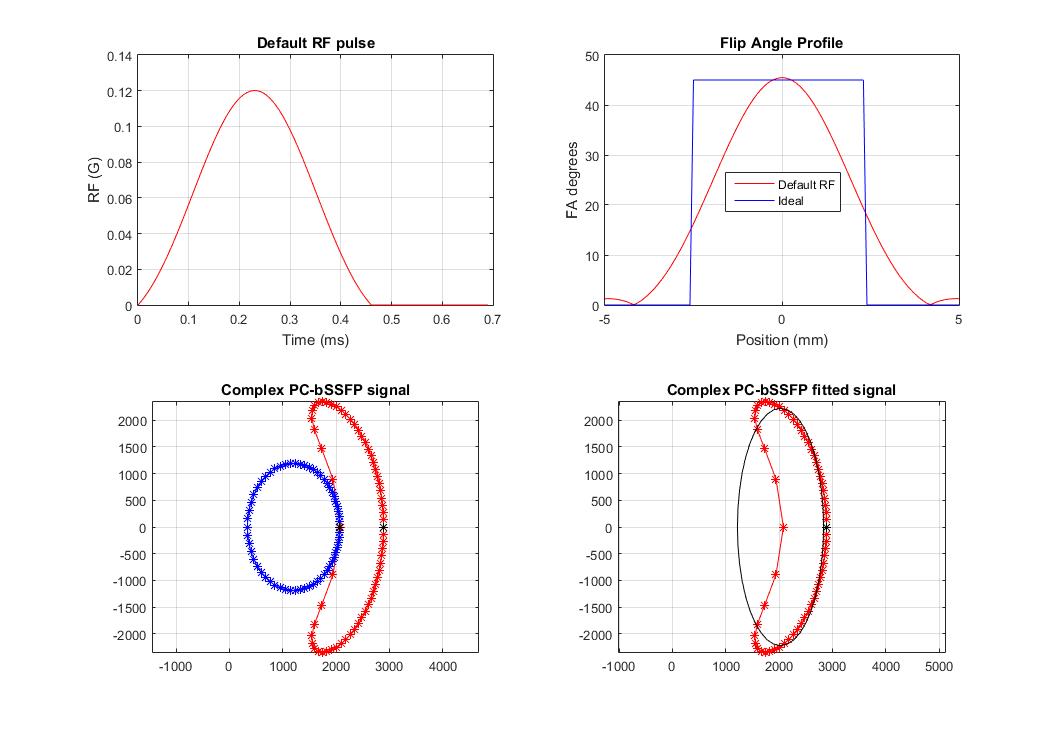
Using a Bloch Simulator, we simulated the behavior of the complex magnetization as a function of resonance offset angle taking into account the slice profile including side lobes outside the slice. Simulations were performed for default and improved RF excitation pulses (improved pulse was selected due to more flat slice profile) and results were compared with the ideal (practically unachievable for 2D) flat slice profile. The initial parameter settings: TR = 15 ms, FA = 45˚, M0 = 10000, T1 = 675 ms, T2 = 75 ms, ∆f0 = 0 Hz, 60 phase cycles with RF phase increments $$$∆\theta_{n}=\frac{2\pi n}{60}, n=\left\{0,1,...59\right\}.$$$
All simulations were performed in Matlab R2015a.
MRI experiments on a phantom (TO5, Eurospin II test system, Scotland) and in vivo (brain of healthy volunteer) were performed on a clinical 1.5T MR scanner (Ingenia, Philips, Best, The Netherlands). A 16-channel head receive coil was used. Datasets with 20 RF phase increment settings were acquired with the same parameter settings as in simulations: 2D bSSFP, FOV 220x220 mm2, slice thickness 5 mm, voxel size 1.5x1.5x5 mm3, TR 15 ms, FA 45˚. Experiments were performed for the default and improved RF pulses.
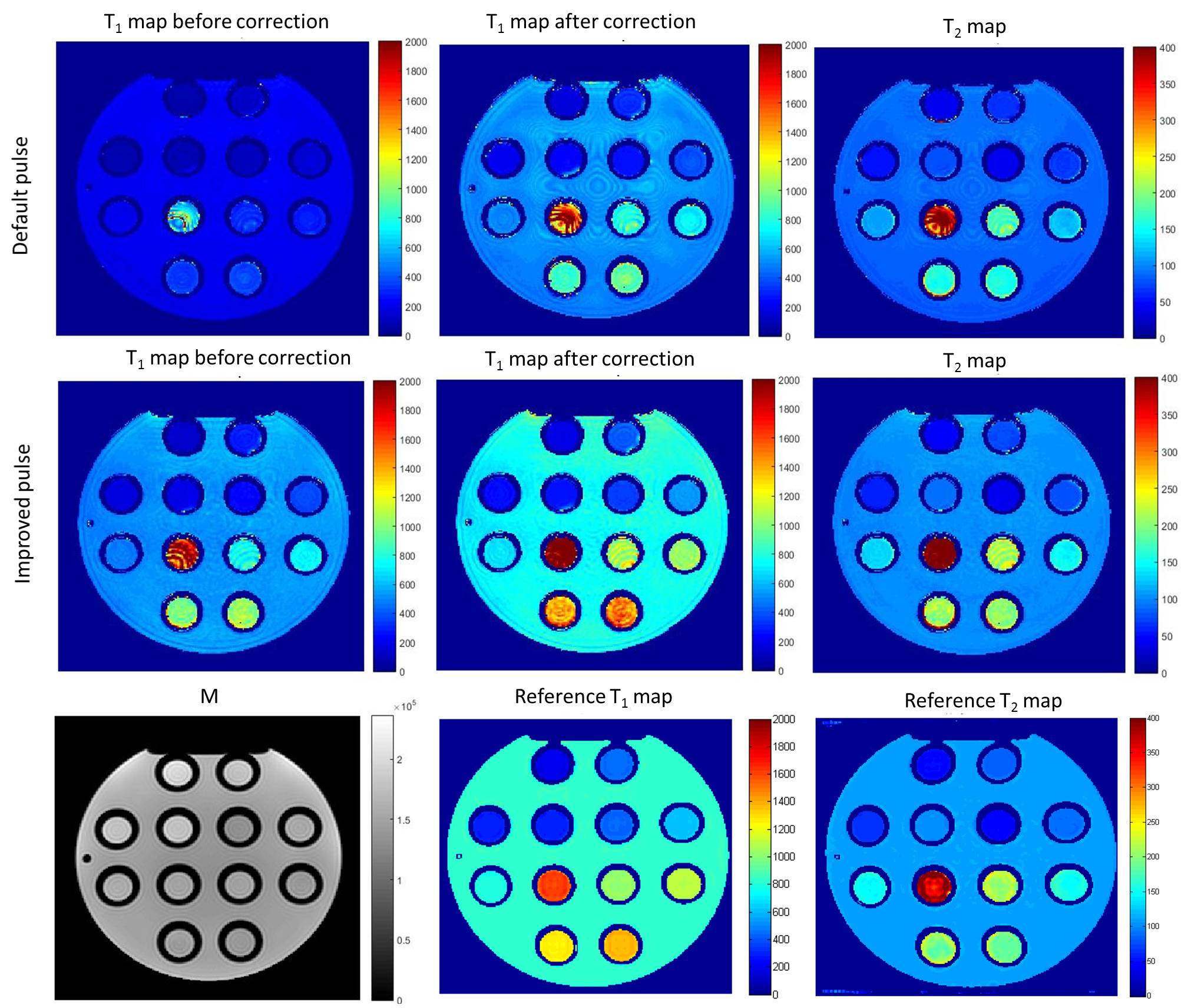
Slice profile correction was performed for the improved and default pulses using the actual flip angle method, proposed by Malik et.al. [4]
To be able to assess the performance of the 2D method, a reference T1 map was calculated from multi TI Inversion Recovery SE data, and a reference T2 map was calculated from multi Echo SE data.
Results
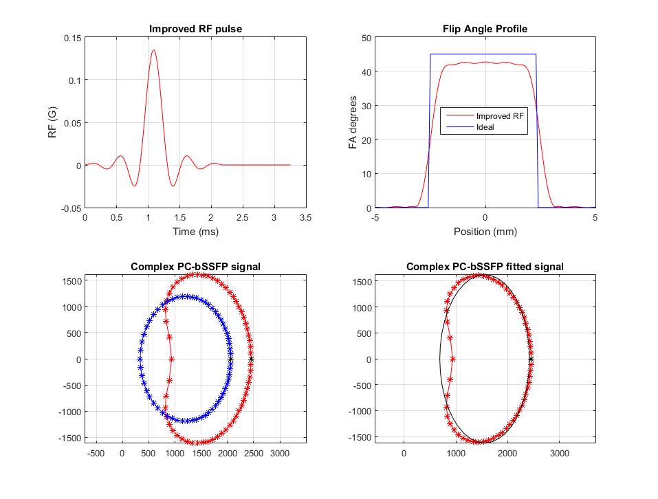
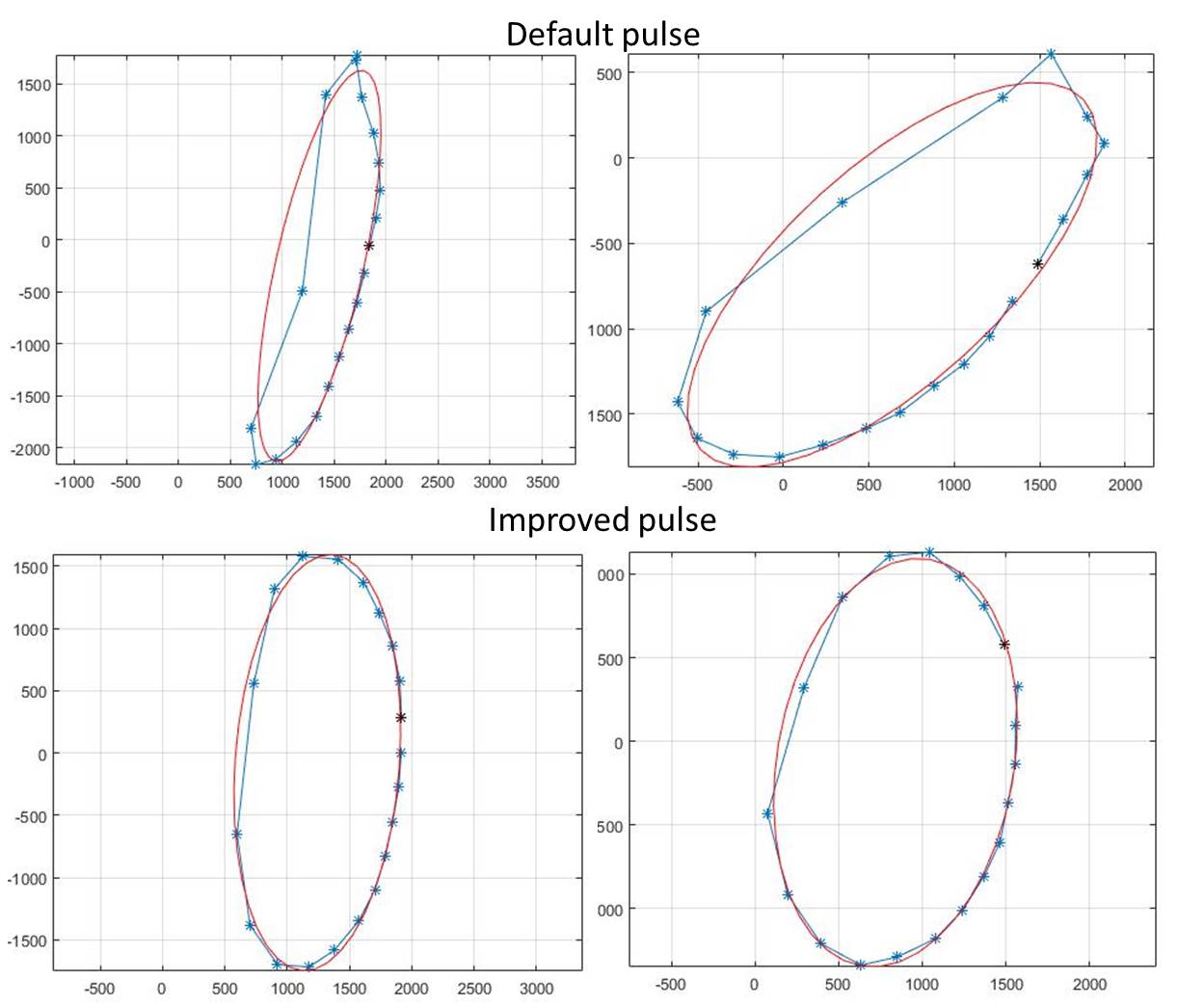
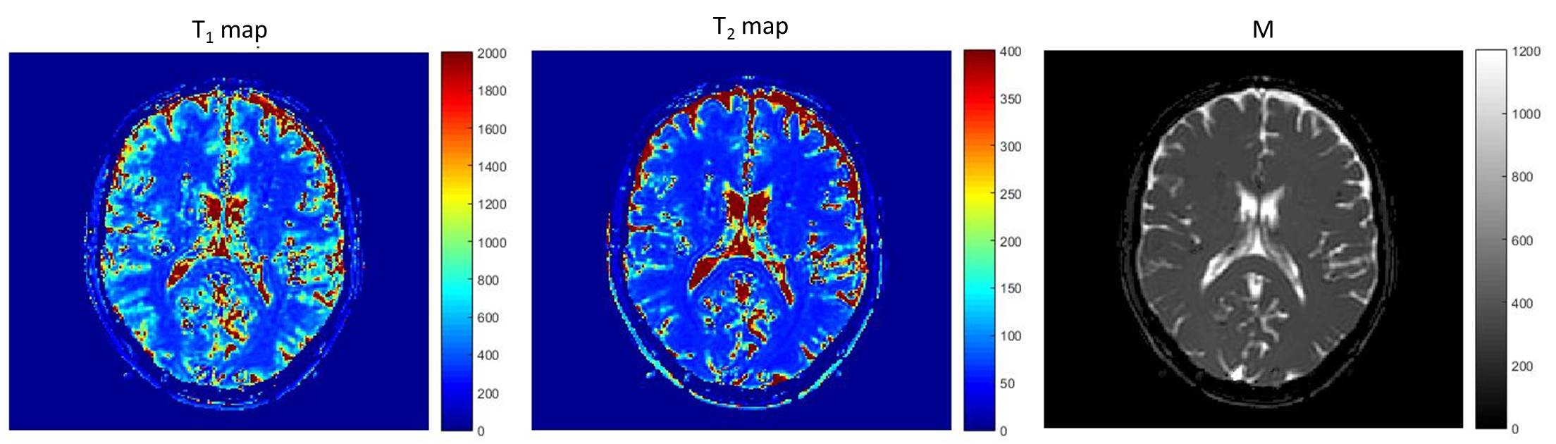
Bloch simulations show that the default RF excitation pulse yields strongly non-elliptical magnetization behavior as a function of the phase setting in the complex plane (Figure 1). With the improved RF pulse the behavior still deviates from the case with the ideal flat profile, but much better resembles an ellipse (Figure 2). The distribution of experimental data points, acquired from the phantom, conforms with the simulations and presented in Figure 3. The T1 and T2 maps of the phantom, calculated for both RF pulses, are shown in Figure 4. The slice profile correction was performed for calculated T1 maps. The mean correction factor was determined as 0.85 for the optimized pulse and 0.65 for the default pulse. The experimental results from in vivo experiment on a brain of healthy volunteer are shown in Figure 5.
Discussion and Conclusion
We have demonstrated that imperfect slice profiles lead to an invalidity of the elliptical steady-state model for PC-bSSFP. We have shown that this compromises PC-bSSFP-based T1 and T2 quantification, which relies on the elliptical behavior of the complex signal. The ideal ellipses are significantly affected by the non-ideal flip angle profile. The severity of this effect will depend on the choice of RF excitation pulse, T1, T2, FA, TR.
Using an improved RF excitation pulse for 2D acquisition mode, resulting in more rectangular slice profile, can mitigate this effect. Nevertheless, we still see a deviation from the ideal elliptical shape even for the improved RF pulse. Fortunately, the ellipse fitting procedure is minimally affected and our experimental results suggest the feasibility of a 2D approach with an optimal RF pulse for the relaxometry purposes. The prolonged RF duration of the improved pulse does not lead to extra scan time as the TR is sufficiently long to accommodate the pulse. Further investigations and optimization of the 2D method are subject of our ongoing research.
Acknowledgements
This research is supported by the Dutch Technology Foundation STW, grant No. 12813References
[1] Shcherbakova et.al. Proc 24th ISMRM, p. 0695 (2016); [2] Lauzon et al. Concepts Magn Reson 34A:133–143 (2009); [3] Xiang et.al. MRM 71:927-933 (2014); [4] Malik et.al. MRM 65:1393–1399 (2011)Figures