5049
A simple optimization approach to making time efficient VERSE-multiband pulses feasible on non-ideal gradients1Division of Imaging Sciences and Biomedical Engineering, King's College London, London, United Kingdom
Synopsis
Multiband pulses can have long durations, which can be reduced by applying the VERSE approach to optimize the combination of gradient and RF pulse to make full use of available hardware performance. The resulting time-varying gradients are demanding and can lead to excitation errors on non-ideal gradient systems. In this work we incorporated the measured gradient impulse response function (GIRF) into an iterative VERSE design method and validated the result using simulation and experiments.
Purpose
Durations of multiband pulses for simultaneous multislice imaging (1) are longer than single-band equivalents. phase-optimizing (2), time-shifting (3) and root-flipping (4) can reduce pulse duration by modifying the relative properties of component slices. These methods use constant selection gradients; further efficiency gains can be achieved by using time-variable gradient waveforms; such methods were used in last year’s ISMRM pulse design challenge (5,6). Time-optimal pulses may demand rapidly varying gradient waveforms, which real gradient systems may not reproduce accurately (7), resulting in excitation errors. However, it has been shown that gradient performance may be modelled as linear time invariant and hence characterized by a gradient impulse response function (GIRF) (8). In this work we developed a simple method to update designs from the Time-optimal VERSE framework (5) using a measured GIRF to produce feasible short-duration multiband waveforms.Theory
When supplied with an RF pulse $$$B_1(t)$$$ and gradient waveform $$$G(t)$$$ the Time-optimal VERSE algorithm will return a minimum duration version $$$B_{1}^{v}(t)$$$ and $$$G^{v}(t)$$$ that has been distorted in time such that either $$$G^{v}(t)$$$ is running at slew/maximum amplitude limits or $$$B_{1}^{v}(t)$$$ is at its maximum value for as much of the duration as possible. The VERSE algorithm optimizes the two waveforms while preserving their ratio: $$W(s)\equiv\frac{B_1(s)}{G(s)}=\frac{B^v_1(s)}{G^v(s)} \quad [1]$$ where s is a k-space arc length parameter defined as $$$s(t) = \gamma \int_{0}^{t} G(\tau)d\tau$$$. Because of non-ideal gradient performances, the demanded gradient waveform $$$G_{dem}$$$ and the realized waveform $$$G_{act}$$$ are not the same, but are related by convolution with an gradient impulse response function (GIRF) $$$H(t)$$$: $$G_{act}(t)=G_{dem}(t) \otimes H(t) \quad [2]$$
The VERSE algorithm deals with $$$G_{dem}$$$ since this is the waveform fed to the scanner, subject to explicit hardware limits. However the magnetization sees $$$G_{act}$$$. Hence, although the VERSE method ensures that $$$G_{dem}^{v}(s) $$$ meets the condition in equation [1], $$$G_{act}^{v}(s)$$$ does not: this violation leads to excitation errors as illustrated in Figure 1. Incorporating equation [2] into the VERSE method is a challenge that is as yet unresolved.
Iterative correction method:
A simple correction can be achieved as follows; run VERSE to find $$$G_{dem}^{v}(t)$$$, then compute $$$G_{act}^{v}(t)$$$ from $$$G_{dem}^{v}(t)$$$ using equation [2]. The realized k-space trajectory can be found by $$s_{act}(t)=\gamma \int_{0}^{t}G_{act}^{v}(\tau)d\tau \quad [3]$$ and the ratio of amplitudes for the realized k-space trajectory $$$W(s_{act})$$$ can be found by resampling $$$W(s)$$$ from the first iteration onto $$$s_{act}(t)$$$. The corrected RF pulse is found as $$$B_1^{v,corr}(s_{act})=G_{act}^{v}(s_{act})W(s_{act})$$$ and is reparametrized to time using equation [3]. However $$$B_{1}^{v,corr}$$$ is not guaranteed to meet its peak amplitude constraint, and will almost certainly violate it. Instead the constraint can be met by feeding $$$B_{1}^{v,corr}$$$ and $$$G_{dem}^{v}$$$ back into the Time-optimal VERSE algorithm and iterating (Figure 2). Convergence is typically achieved within 100 iterations (computation time 3-5 minutes on i7-4810MQ CPU @ 2.80GHz).
Methods
Numerical Simulations
Phase-optimized multiband pulses (90° excitation and 180° refocusing, TBP=4) were designed for a range of multiband factors and slice separations and Time-optimal VERSE applied as described in (5) (Figure 1b, maximum gradient amplitude 40 mTm-1 and slew 200 mTm-1s-1, peak $$$B_{1}=13\mu T$$$). Modified designs were then produced using a GIRF for a Philips Achieva 3T system, which was estimated using image-based gradient measurements combined with chirp-based gradient waveforms with different bandwidths.
Experiments
This method was validated on the described 3T system by measuring slice profiles for excitation pulses in a doped water phantom ($$$T_1$$$ = 270ms) using a gradient echo sequence with the RF flip angle scaled to 20° to avoid saturation effects.
Results
Simulation results for a range of multiband factors and slice separations are shown in Figure 4. Time-optimal VERSE reduced the duration of phase-optimized pulses by 80%, and root-flipped by 46% on average. The resulting rapidly modulated gradient waveforms lead to excitation errors, as shown on Figure 5; the proposed method significantly improves the slice profiles acquired in practice. Once corrected, phase-optimized pulses are 70% shorter than constant gradient, while the figure is 31% for root-flipped pulses.Discussion and Conclusion
Time-optimal VERSE is a very effective method for reducing durations of multiband RF pulses, particularly for phase-optimized pulses, whose performance after VERSE is similar to the root-flipped pulses (Figure 4). The resulting very rapid gradient modulation is however hard to realise in practice. We propose an iterative method for accounting for gradient imperfections that may be used if the impulse response function of the gradient system is known. Experimental results demonstrate the value of this approach. Further improvements could be achieved fully incorporating the GIRF into a combined RF and gradient optimization. This is the focus of future work.Acknowledgements
This work is funded by the King’s College London & Imperial College London EPSRC Centre for Doctoral Training in Medical Imaging (EP/L015226/1) and by MRC strategic grant (MR/K0006355/1).
SJM acknowledges support from the EPSRC (EP/L00531X/1).
Publicly available code for root-flipped pulses from Sharma et al was downloaded from http://www.vuiis.vanderbilt.edu/~grissowa/.
References
1. Larkman DJ, Hajnal J V, Herlihy AH, Coutts GA, Young IR, Ehnholm G. Use of multicoil arrays for separation of signal from multiple slices simultaneously excited. J. Magn. Reson. Imaging 2001;13:313–317.
2. Wong E. Optimized phase schedules for minimizing peak RF power in simultaneous multi-slice RF excitation pulses. Proc. Intl. Soc. Mag. Reson. Med. 20 2012;20:2209.
3. Auerbach EJ, Xu J, Yacoub E, Moeller S, Ugurbil K. Multiband accelerated spin-echo echo planar imaging with reduced peak RF power using time-shifted RF pulses. Magn. Reson. Med. 2013;69:1261–1267. doi: 10.1002/mrm.24719.
4. Sharma A, Lustig M, Grissom WA. Root-flipped multiband refocusing pulses. Magn. Reson. Med. 2016;75:227–237. doi: 10.1002/mrm.25629.
5. Lee D, Lustig M, Grissom WA, Pauly JM. Time-optimal design for multidimensional and parallel transmit variable-rate selective excitation. Magn. Reson. Med. 2009;61:1471–1479. doi: 10.1002/mrm.21950.
6. Aigner CS, Clason C, Rund A. Low SAR RF-pulse design by joint optimization of RF and gradient shape with physical constraints. In: Proc. Intl. Soc. Mag. Reson. Med. 24. ; 2016.
7. Grissom WA, Setsompop K, Hurley SA, Tsao J, Velikina J V., Samsonov AA. Advancing RF pulse design using an open-competition format: Report from the 2015 ISMRM challenge. Magn. Reson. Med. 2016;0:1–10. doi: 10.1002/mrm.26512.
8. Vannesjo SJ, Haeberlin M, Kasper L, Pavan M, Wilm BJ, Barmet C, Pruessmann KP. Gradient system characterization by impulse response measurements with a dynamic field camera. Magn. Reson. Med. 2013;69:583–593. doi: 10.1002/mrm.24263.
Figures
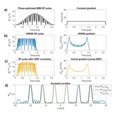
Figure 1:
a) Phase-optimized multiband 6 waveforms.
b) The multiband waveforms after the Time-optimal VERSE.
c) The multiband waveforms after GIRF is taking into account. The $$$B_{1}^{v,corr}$$$ is corrected based on the constant gradient waveforms.
d) Slice profile comparison for the three methods. The original slice profile is simulated using the ideal constant gradient, whilst the other slice profiles are simulated using the predicted non-ideal gradient (shown in c).
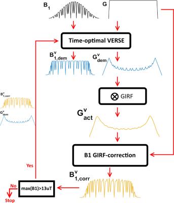
Figure 2:
Pipeline of the iterative optimization method. Starting from any combination of $$$B_1$$$ and gradient waveform, the waveform are improved by the Time-optimal VERSE method. The output $$$B_{1}^{v}$$$ waveform is discarded, and the gradient waveform is convolved with the GIRF to simulate the effect of a real gradient system. The GIRF-corrected $$$B_{1}^{v,corr}$$$ waveform is calculated such that it gives the exact same slice profile as the original waveforms. The algorithm reiterates on $$$B_1^{v,corr}$$$ and the $$$G_{dem}^{v}$$$ waveforms such that it conditions itself into producing a $$$B_1^{v}$$$ waveform which matches the GIRF-correction.
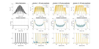
Figure 3:
Results from before optimization, and the first, fifth and twelfth iteration for a multiband six pulse. In the first iteration there is a clear difference between the VERSE-output waveform (blue) and corrected RF waveform (yellow). Bottom row shows the excitation profile based on the non-ideal gradient. After multiple iterations the difference between $$$B_1$$$-waveforms, and hence their slice-profiles, becomes negligible and the original peak-$$$B_1$$$ requirement is met.
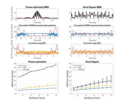
Figure 4:
Simulated results showing efficiency of the algorithm for phase-optimized and root-flipped refocusing pulses with Time-bandwidth product 4. Effective duration is defined as the duration of the pulse relative to the duration of a block-pulse with equal peak amplitude and flip angle. The main trace shows the average results over inter-slice separations of 3 to 16 slices. Error-bars show the minimum and maximum duration across all slice separations. The VERSE + GIRF technique is less efficient than the VERSE only method. Interestingly, both VERSE versions of phase-optimized and root-flipped pulses have similar effective duration.
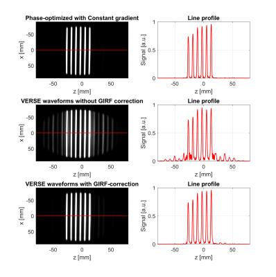
Figure 5:
Experimental results at 3T. The top-row shows slice profiles using a phase-optimized multiband 6 pulse.
Middle row: By using VERSE, the duration is decreased but the rough gradient waveform cannot be physically realized by the system. Consequently a distorted slice profile is measured.
Bottom row: By using the VERSE waveforms which incorporate the GIRF, the slice profile is significantly improved.